Half Wave Rectifier with Capacitor Filter:
Half Wave Rectifier with Capacitor Filter – When a sinusoidal alternating voltage is rectified, the resultant waveform is a series of positive (or negative) half-cycles of the input waveform; it is not direct voltage. To convert to direct voltage (dc), a smoothing circuit or filter must be employed.
Figure 3-7(a) shows a Half Wave Rectifier with Capacitor Filter (C1) and a load resistor (RL). The capacitor, termed a reservoir capacitor, is charged almost to the peak level of the circuit input voltage when the diode is forward biased. This occurs at Vpi as shown in Fig. 3-7(b), giving a peak capacitor voltage,
![]()
When the instantaneous level of input (at the diode anode) falls below Vpi the diode becomes reverse biased, because the capacitor voltage (VC) (at the diode cathode) remains close to (Vpi – VF), [see Fig. 3-7(c)]. With the diode reverse biased, the capacitor begins to discharge through the load resistor (RL). So, VC falls slowly, as shown by the capacitor voltage waveform in Fig. 3-7(a).
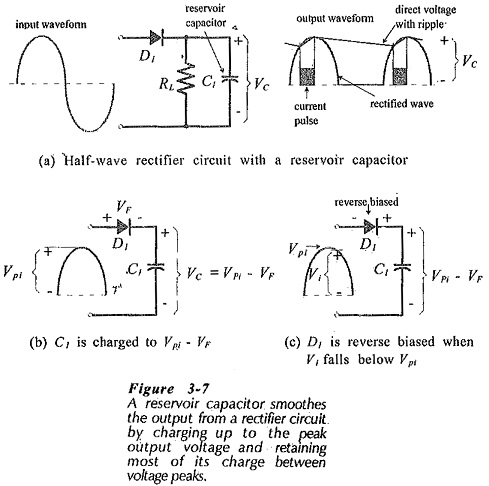
The diode remains reverse biased through the remainder of the input positive half-cycle, the negative half-cycle, and the first part of the positive half-cycle again until the instantaneous level of V1 becomes greater than VC once more. At this point current flows through the diode to recharge the capacitor, causing the capacitor voltage to return to (Vpi – VF). The charge and discharge of the capacitor causes the small increase and decrease in the capacitor voltage, which is also the circuit output voltage. It is seen that the circuit output is a .direct voltage with a small ripple voltage waveform superimposed, Wig. 3-7(a)].
Capacitance Calculation:
The amplitude of the ripple voltage is affected by the load current, the reservoir capacitor value, and the capacitor discharge time. The discharge time depends upon the frequency of the ripple waveform, which is the same as the ac input frequency in the case of a Half Wave Rectifier with Capacitor Filter. With a constant load current, the ripple amplitude is inversely proportional to the capacitance; the largest capacitance produces the smallest ripple.
The capacitance for the reservoir capacitor can be calculated from the load current, the acceptable ripple amplitude, and the capacitor discharge time. Consider the circuit output voltage waveform illustrated in Fig. 3-8(a).
The waveform quantities are:
Eave – average dc output voltage
Eo(max) – maximum output voltage level
Eo(min) – minimum output voltage
Vr – ripple voltage peak-to-peak amplitude
T – time period of the ac input waveform
t1 – capacitor discharge time
t2 – capacitor charge time
θ1 – phase angle of the input wave from zero to Eo(min)
θ2 – phase angle of the input wave from Eo(min) to Eo(max)
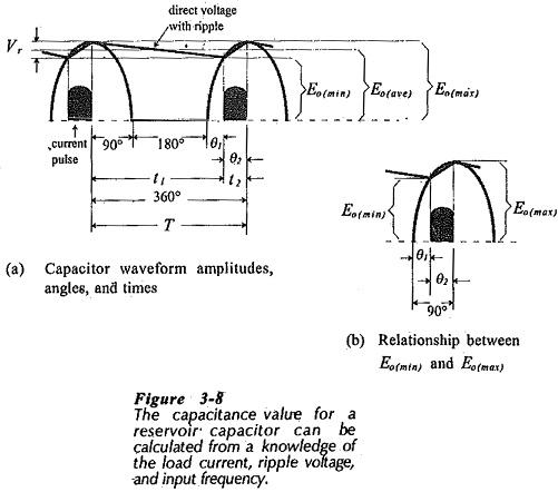
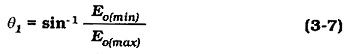
Figure 3-8(b) shows that, because the input wave is sinusoidal,
![]()
which gives,
Also from Fig. 3-8(b),
![]()
The time period is,
where f is the frequency of the ac input waveform.
During T, the input waveform goes through a 360° phase angle, which gives the time per degree as,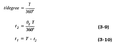
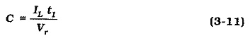
Taking the current as a constant quantity,
Capacitor Selection:
When a capacitance value is calculated, an appropriate capacitor has to be selected from a manufacturer’s list of available standard values. With a reservoir capacitor, the calculated capacitance is always the minimum value required to give a specified maximum ripple voltage amplitude. If a larger-than-calculated capacitance is used, the ripple voltage will be lower than the specified maximum. So, a larger standard value capacitor is always selected in the case of a reservoir capacitor.
The standard-value capacitors are typically available with +20% tolerance. In the case of capacitors greater than 10 pF, the tolerance is often listed as -10% +50%. This means that a 100 μF capacitor might have a capacitance as low as 90 μF, or as high as 150 μF. In most circuit situations, a minimum capacitance value is calculated, and a larger value is quite acceptable.
The voltage that a capacitor will be subjected to must be taken into consideration. The maximum voltage that may be safely applied to a capacitor is stated in terms of its dc working voltage. The dc working voltages can be quite small for large-value capacitors. For example, some 10 μF capacitors have 6.3 V working voltages. The capacitor dielectric may break down if the specified voltage is exceeded.
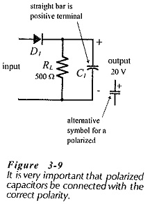
Capacitor Polarity:
It is very important that polarized capacitors be correctly connected. Sometimes polarized capacitors explode when they are incorrectly connected, and this could have tragic consequences for the eyes of an experimenter. The positive terminal is represented by the straight bar on the component graphic symbol, or identified by the plus sign on the alternative symbol, (see Fig. 3-9). This should be connected to the most positive point in the circuit where the capacitor is to be installed. Non-polarized capacitors should be used in situations where the voltage polarity might be reversed.
Approximate Calculations:
The capacitance calculation shows that the load current is a constant quantity. This is an approximation, because the load current changes by a small amount as the output voltage increases and decreases. Normally, the load current change is so small that it has no significant effect on the calculation.
Another approximation that can be made to simplify the capacitance calculation is to take the discharge time (t1) as equal to the input waveform time period (T), [see Fig. 3-8(a)].
![]()
Equation 3-12 assumes that the capacitor charging time (t2) is so much smaller than t1 that it can be neglected. This is a reasonable assumption where the ripple voltage is small. Also, use of Eq. 3-12 gives a larger capacitance value than the more precise calculation, and this is acceptable because a larger-than-calculated standard value capacitor is normally selected.
Diode Specification:
Rectifier diodes must be specified in terms of the currents and voltages that they are subjected to. The calculated levels are normally minimum quantities, and the selected diodes must be able to survive higher levels.
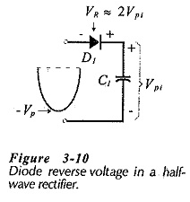
Consider Fig. 3-10 which illustrates the situation when the ac input wave is at its negative peak voltage (-Vp). The capacitor has already been charged up to approximately the positive peak level of the input (+Vp). Consequently, the diode has -Vp at its, anode and +Vp at its cathode, so the diode peak reverse voltage is,
![]()
The average forward rectified current (IF(av)) that the diode must pass is equal to the dc output current.
![]()
The diode in a half-wave rectifier circuit with a reservoir capacitor does not conduct continuously, but repeatedly passes pulses of current to recharge the capacitor each time the diode becomes forward biased. This is illustrated in Fig. 3-8 and again in Fig. 3-11.
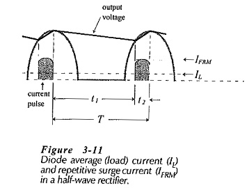
The current pulse is known as the repetitive surge current, and is designated (IFRM). The average input current to the rectifier circuit must equal the average load current (IL), so IFRM averaged over time period T equals IL . (see Fig. 3-11)
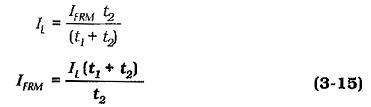
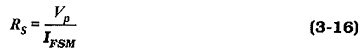
Figure 3-12 shows a half-wave rectifier circuit with a resistor (RS) connected in series with the diode. This is a low-resistance component known as a surge limiting resistor. As its name suggests, the purpose of RS is to limit the level of any surge current that might pass through the diode. The highest surge current occurs when the ac supply is first switched on to the rectifier circuit. Before switch-on, the reservoir capacitor normally contains no charge, so it behaves as a short-circuit at the instant of switch-on. If switch-on occurs when the ac input is at its peak level, the surge current is,
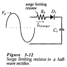
For a diode with a specified maximum non-repetitive surge current (IFSM), the surge limiting resistor is calculated as,