Classification of Transmission Lines:
Classification of Transmission Lines are usually classified as
- Lines with no loss or ideal lines,
- Lines without distortion or distortion less lines
- Lines with small losses, and
- Lines with infinite and finite length defined by all the four parameters.
1.Lines with no loss or ideal lines
A line is said to be an ideal line if R = 0 and G= In this case the surge impedance of the line is Z = √L/C and the surge admittance of the line is Y = √C/L. The solution for the voltage and current waves for this type of Classification of Transmission Lines is obtained as
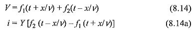
The function f2(t – x/v) represents the forward travelling wave and the function f1(t + x/v) represents the backward travelling wave. The propagation velocity for either wave is given as
![]()
2.Lines without distortion or distortion less lines
If, for any line R/L = G/C= α
then, γ = √ZY = √LC (s+α) and the surge impedance is
![]()
For these conditions, the solution for the wave equations (8.10) and (8.I0a) will be modified as
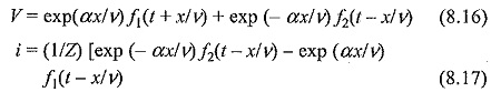
The voltage and current waves for an ideal line represented by equations (8.14) and (8.14a) will be of the same shape. However, for a distortionless line, their magnitudes will decrease by the factor exp (± αx/v), which is the reduction with respect to the distance x. The solutions can be rearranged by putting
![]()
Under these conditions,
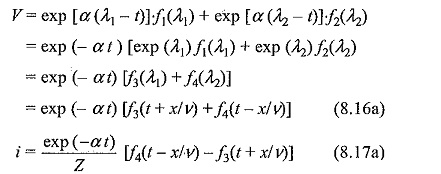
Thus the attenuation can be either with respect to the distance, x or the time, t. Equations (8.16) and (8.17) are more useful if the voltage distribution at t = 0 (initial condition) is specified.
3.Lines with small losses
Line with small losses In this type of lines, the time constants of the Classification of Transmission Lines are large, i.e. R/L and G/C are small. Then γ can be approximated to be equal to (s + α/v), and Y(s) to be equal to √C/L (1 – β/s). Under these conditions, the solutions for the voltage and the current waves become
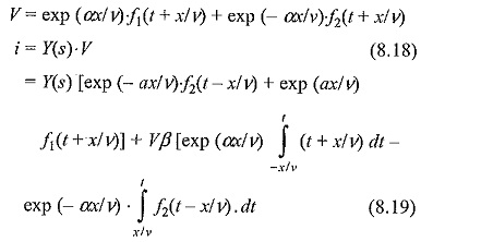
The voltage Eq. (8.18) is similar to Eq. (8.14) and the current Eq. (8.19) is similar to Eq. (8.14a), along with the other expression containing the time integral of the functions f1 and f2.
In a Classification of Transmission Lines with small losses, voltage solution shows that the voltage wave is the same as that in the case of distortion] ess line. However, the solution for the current wave differs by an amount equal to the energy loss in the resistance of the line. Thus, this is solution valid only for small intervals of time, i.e. for small values of (t + x/v).
4.Lines with infinite and finite length defined by all the four parameters
Exact solution for lines of finite or infinite length defined by all the four parameters The exact solution of the wave equation of this type of lines is quite complex and is normally of little practical importance. However, some of the inferences that can be drawn are:
- the current and the voltage wave are dissimilar
- the attenuation and distortion due to normal line resistance and leakage conductance are of little consequence
-
the surge impedance Z(s) = e(s) / i(s) is a complex function and is not uniquely defined.