Sag in Overhead Transmission Lines:
While erecting an Sag in Overhead Transmission Lines, it is very important that conductors are under safe tension. If the conductors are too much stretched between supports in a bid to save conductor material, the stress in the conductor may reach unsafe value and in certain cases the conductor may break due to excessive tension. In order to permit safe tension in the conductors, they are not fully stretched but are allowed to have a dip or sag.
The difference in level between points of supports and the lowest point on the conductor is called sag.
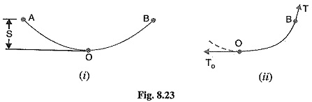
Fig. 8.23. (i) shows a conductor suspended between two equilevel supports A and B. The conductor is not fully stretched but is allowed to have a dip. The lowest point on the conductor is 0 and the sag is S. The following points may be noted :
- When the conductor is suspended between two supports at the same level, it takes the shape of catenary. However, if the sag is very small compared with the span, then sag-span curve is like a parabola.
- The tension at any point on the conductor acts tangentially. Thus tension TO at the lowest point O acts horizontally as shown in Fig. 8.23. (ii).
- The horizontal component of tension is constant throughout the length of the wire.
- The tension at supports is approximately equal to the horizontal tension acting at any point on the wire. Thus if T is the tension at the support B, then T = TO.
Conductor sag and tension. This is an important consideration in the mechanical design of overhead lines. The conductor sag should be kept to a minimum in order to reduce the conductor material required and to avoid extra pole height for sufficient clearance above ground level. It is also desirable that tension in the conductor should be low to avoid the mechanical failure of conductor and to permit the use of less strong supports. However, low conductor tension and minimum sag are not possible. It is because low sag means a tight wire and high tension, whereas a low tension means a loose wire and increased sag. Therefore, in actual practice, a compromise in made between the two.
Calculation of Sag in Overhead Transmission Lines:
In an overhead line, the sag should be so adjusted that tension in the conductors is within safe limits. The tension is governed by conductor weight, effects of wind, ice loading and temperature variations. It is a standard practice to keep conductor tension less than 50% of its ultimate tensile strength i.e., minimum factor of safety in respect of conductor tension should be 2.
We shall now calculate sag and tension of a conductor when
- supports are at equal levels and
- supports are at unequal levels.
1.When supports are at equal levels.
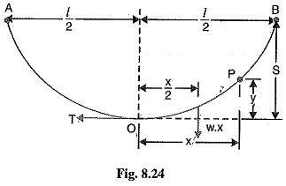
Consider a conductor between two equilevel supports A and B with O as the lowest point as shown in Fig. 8.24. It can be proved that lowest point will be at the mid-span.
Let
l = Length of span
w = Weight per unit length of conductor
T = Tension in the conductor.
Consider a point P on the conductor. Taking the lowest point O as the origin, let the co-ordinates of point P be x and y. Assuming that the curvature is so small that curved length is equal to its horizontal projection (i.e., OP = x), the two forces acting on the portion OP of the conductor are :
- The weight wx of conductor acting at a distance x/2 from O.
- The tension T acting at O.
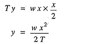
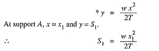
Equating the moments of above two forces about point O, we get,
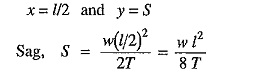
The maximum dip (sag) is represented by the value of y at either of the supports A and B.
At support A,
2.When supports are at unequal levels.
In hilly areas, we generally come across conductors suspended between supports at unequal levels. Fig. 8.25 shows a conductor suspended between two supports A and B which are at different levels. The lowest point on the conductor is O.
Let
l = Span length
h = Difference in levels between two supports
x1 = Distance of support at lower level (i.e., A) from O
x2= Distance of support at higher level (i.e. B) from O
T = Tension in the conductor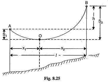
If w is the weight per unit length of the conductor, the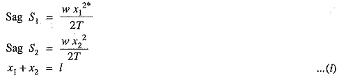 n,
n,
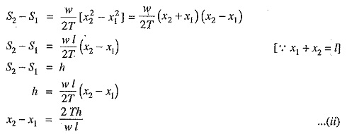
Solving exps. (i) and (ii), we get,
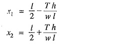
Having found x1 and x2, values of S1 and S2 can be easily calculated.
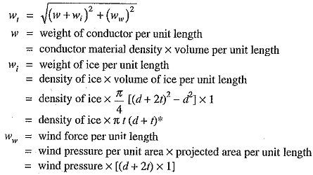
Effect of wind and ice loading. The above formulae for Sag in Overhead Transmission Lines are true only in still air and at normal temperature when the conductor is acted by its weight only. However, in actual practice, a conductor may have ice coating and simultaneously subjected to wind pressure. The weight of ice acts vertically downwards i.e., in the same direction as the weight of conductor. The force due to the wind is assumed to act horizontally i.e., at right angle to the projected surface of the conductor. Hence, the total force on the conductor is the vector sum of horizontal and vertical force as shown in Fig. 8.26 (iii).
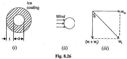
Total weight of conductor per unit length is
When the conductor has wind and ice loading also, the following points may be noted :
1.The conductor sets itself in a plane at an angle θ to the vertical where
![]()
2.The sag in the conductor is given by
![]()
Hence S represents the slant sag in a direction making an angle θ to the vertical. If no specific mention is made in the problem, then slant slag is calculated by using the above formula.
3.The vertical sag = S cos θ