Cold Cathode Gas Filled Diode:
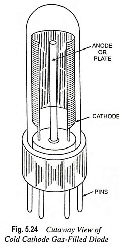
The cutaway view of a Cold Cathode Gas Filled Diode is shown in Fig. 5.24. It essentially consists of two electrodes, namely cathode and anode, mounted fairly close together in a glass envelope. The anode is in the form of a thin wire, while cathode is of cylindrical metallic surface having oxide coating. The anode (or plate) is always held at positive potential with respect to cathode.
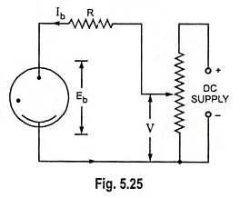
Circuit arrangement for studying the operation of a Cold Cathode Gas Filled Diode is shown in Fig. 5.25. The positive terminal of variable dc supply is connected to the anode through a current limiting resistor R and negative to the cathode. On increasing the applied voltage between anode and cathode, electric conduction through the tube passes through three successive discharge phases viz. Townsend discharge, the glow discharge and the arc discharge, as illustrated in Fig. 5.26.
When applied voltage (anode-cathode voltage, Eb) is low, the tube conducts an extremely small current (say few μA) because the cathode is cold and as such no source of electrons is present. However, some ionization of gas is caused by natural sources, such as cosmic rays etc., and a few free electrons are produced. These free electrons move towards the anode and constitute a small current in the circuit. This stage of conduction is known as Townsend discharge, after the name of J.S. Townsend who investigated the V-I characteristics of Cold Cathode Gas Filled Diode (glow tube) for the first time in 1901. In this phase of conduction, no visible light is associated and the current is known as dark current.
As the applied voltage is increased, the electrons acquire more and more energy and stage, known as ionization or striking or breakdown voltage, arrives when the gas starts getting ionized and the tube current rises dramatically to a large value. The voltage drop across the tube Eb drops to a low value because of decrease in the internal resistance of tube due to ionization of gas. This voltage drop across the tube, Eb remains constant regardless of plate current Ib. Simultaneously glow is seen in the gas and on a portion of the cathode. That is why this phase of conduction is known as glow discharge. In the glow discharge region, the glow tube maintains a constant voltage across it although there is an appreciable increase in tube current Ib. This is explained as below:
In this region, increase in supply voltage V causes increase in plate current Ib which increases the voltage drop in the series resistor R but the voltage across the tube Eb remains constant. This is only possible if the internal resistance of the tube decreases with the increase in its current and that is exactly what happens in the tube. With the increase in tube current, the degree of ionization increases and the glow covers a greater part of the cathode surface. Thus cross section area of ionized gas path between anode and cathode is increased and internal resistance of the tube, being inversely proportional to the area of x-section, decreases. Hence, the voltage across the tube, Eb, in the glow discharge region remains constant.
If the supply voltage V is further increased gradually, a stage arrives when cathode glow covers the entire surface of the cathode and there is no further increase in cross-sectional area of gas path if supply voltage is increased beyond this stage. This region is known as abnormal glow region. If the current density is further increased. the discharge gets converted into an arc and hence known as arc discharge.
Cold Cathode Gas Filled Diode Characteristics:
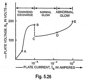
The volt-ampere characteristic of a Cold Cathode Gas Filled Diode is shown in Fig. 5.26. At low anode-cathode voltage, the discharge is because of minor ionization of gas due to external sources such as cosmic rays etc. and tube current is, therefore, very small. This region, which extends up to point B, is called the Townsend discharge region. It is a non-self maintained discharge because it needs an external source to cause ionization. At point B, the tube fires and the voltage across the tube Eb drops from point B to point C and remains constant regardless of plate current Ib. This is the beginning of the second conduction known as normal glow discharge region. In the region extending from C to D, voltage across the tube remains constant though the plate current increases. After the glow discharge (point D), the voltage across the tube no longer remains constant. With the increase in supply voltage V, not only the circuit current increases but voltage across the tube, Eb also starts increasing. This region of conduction (D to E) is known as abnormal glow discharge region.
Applications of Cold Cathode Gas Filled Diode (or Glow Tube):
The Cold Cathode Gas Filled Diode or glow tube has an outstanding characteristic of maintaining constant voltage across it in the normal glow discharge region. This unique characteristic renders it suitable for many industrial and control applications. A few of such applications are enumerated here.
- As a voltage regulating tube. The outstanding characteristic of maintaining constant voltage across it in the glow discharge region permits its use as a voltage regulating tube i.e. to maintain constant voltage across a load.
- As a polarity indicator. As the cathode of this tube is surrounded by a characteristic glow, it can be, therefore, employed to indicate the polarity of a direct voltage.
- As an electronic switch. As it closes at ionization potential, permitting a large current to flow and opens at the deionization potential blocking the flow of current, it can be used as an electronic switch.
- As a radio frequency field detector. As a strong radio-frequency field is capable of ionizing the gas filled in this tube without making any direct connection to the tube, this tube can he employed to indicate the presence of radio-frequency (RF) field at any place.