UJT Triggering of SCR Working Principle:
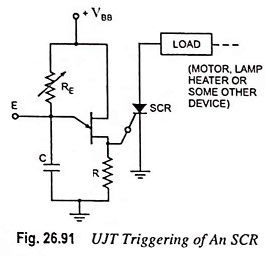
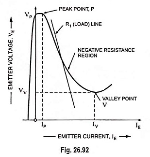
UJT Triggering of SCR Working Principle – One common application of the unijunction transistor is the triggering of the other devices such as the SCR, triac etc. The basic elements of such a triggering circuit are shown in Fig. 26.91. The resistor RE is chosen so that the load line determined by RE passes through the device characteristic in the negative resistance region i.e., to the right of the peak point but to the left of the valley point, as shown in Fig. 26.92. If the load line does not pass to the right of the peak point P, the device cannot turn on.
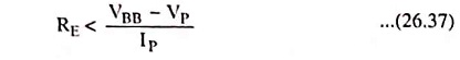
For ensuring turn-on of UJT
This can be established as below :
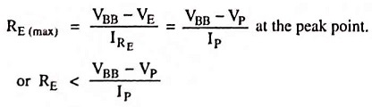
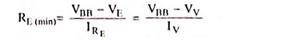
Consider the peak point at which IRE = IP and VE = VP (the equality IRE = IP is valid because the charging current of capacitor at this instant is zero i.e., the capacitor, at this particular instant, is changing from a charging state to a discharging state). Then VE = VBB – IRERE.
So
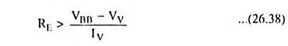
At the valley point, V
IE = IV and VE = VV so that
So
or for ensuring turn-off
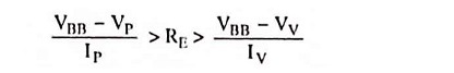
So the range of resistor RE is given as
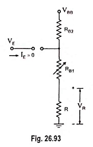
The resistor R is chosen small enough so as to ensure that SCR is not turned on by voltage VR when emitter terminal E is open or IE = 0 (Fig. 26.93). The Voltage VR = RVBB/R + RBB for open-emitter terminal.
The capacitor C determines the time interval between triggering pulses and the time duration of each pulse.
By varying RE, we can change the time constant REC and alter the point at which the UJT fires. This allows us to control the conduction angle of the SCR, which means the control of load current.