SCR Applications Circuits:
SCR Applications Circuits : An SCR circuit is stable when it operates correctly: switching on and off only at the desired instants. Unwanted triggering (also called false triggering) can be produced by noise voltages at the gate, transient voltages at the anode terminal, or by very fast voltages changes at the anode (termed dv/ dt triggering).
Obviously, gate noise voltages might be large enough to forward bias the gate-cathode junction and cause false triggering. Anode voltage transients (produced by other devices connected to the same ac supply) could exceed the SCR breakover voltage, and thus trigger it into conduction. The dv/dt effect occurs when the anode voltage changes instantaneously, such as when the supply is switched on at its peak voltage level. The SCR capacitance is charged very quickly, and the charging current is sufficient to trigger the device.
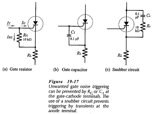
Gate noise problems can be minimised by keeping the gate connecting leads short, and by the use of a gate bias resistor [RG in Fig. 19-17(a)]. This should be connected as close as possible to the SCR gate-cathode terminals, because connecting conductors between RG and the device could pick up noise that might cause triggering. Biasing the gate negative with respect to the cathode can also be effective in combating noise. Capacitor C1 in Fig. 19-17(b) can be used to short circuit gate noise voltages. C1 also operates in conjunction with the anode-gate capacitance as a voltage divider that reduces the possibility of dv/dt triggering. C1 is usually in the 0.01 μF to 0.1 μF range, and like RG, it should be connected close to the SCR terminals.
An RC snubber circuit can be used to prevent triggering by anode terminal transients, [Fig. 19-17(c)]. A snubber is usually necessary for inductive loads, and might also be required for resistive loads. With an ac supply, there is a phase difference between an inductive load current and the supply voltage, and this can cause loss of SCR control. Also, the current through an inductor with a dc supply will not go to zero immediately when the SCR switches off. A snubber circuit is necessary in both cases.
Zero-Point Triggering:
When an SCR is switched on while the instantaneous level of the supply voltage is greater than zero, surge currents occur that generate electromagnetic interference (EMI). The EMI can interfere with other nearby circuits and equipment, and the switching transients can affect control of the SCR Applications Circuits. Circuits can be designed to trigger an SCR on at the instant the ac supply is crossing the zero voltage point from the negative half-cycle to the positive half-cycle. This is called zero-point triggering, and it effectively eliminates the EMI and the switching transients.
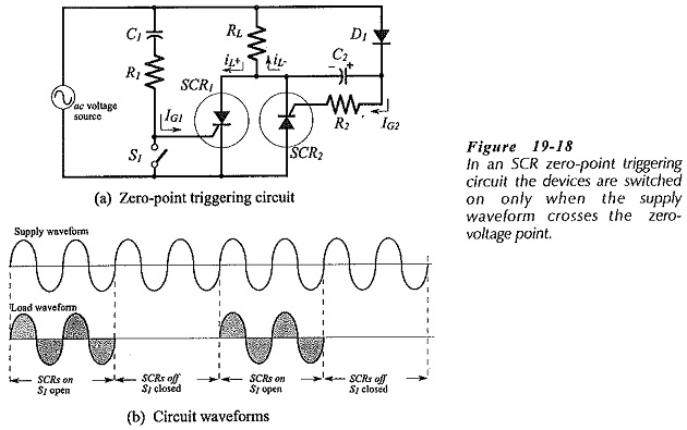
The zero-point triggering circuit in Fig. 19-18(a) shows two inverse-parallel connected SCRs that each have RC triggering circuits; C1 and R1 for SCR1, and C2 and R2 for SCR2. SCR1 is held off while switch S1 is closed, and because capacitor C2 is uncharged SCR2 remains off. With S1 open, positive triggering current (IG1) begins to flow when the supply voltage commences to go positive. As illustrated, IG1 flows via C1 and R1 to the gate of SCR1 triggering it into conduction at the zero-crossing point. SCR1 provides a path for (positive) load current (iL+).
With SCR1 on, capacitor C2 charges (with the polarity shown) almost to the peak of the supply voltage. When the supply voltage crosses zero from the positive half-cycle to the negative half-cycle SCR1 switches off Also, D1 becomes reverse biased, and the charge on C1 provides triggering current (IG2) to SCR2. Thus, SCR2 is switched on at the start of the supply negative half-cycle, providing a path for (negative) load current (iL).
Both SCR Applications Circuits continue to switch on and off at the zero-crossing points while S1 remains open, and both stay off when S1 is closed. SCR2 cannot switch on unless SCR1 has first been on, and because of this the arrangement is sometimes termed a master-slave circuit; SCR1 being the master and SCR2 the slave. The waveforms in Fig. 19-18(b) show that power is supplied to the load for several cycles of the supply while S1 is open, and no load power dissipation occurs for several cycles while S1 remains closed. The switch might be controlled by a temperature sensor or other device.
Crowbar Circuit:
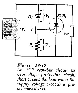
A crowbar circuit (also known as an overvoltage protection circuit) is illustrated in Fig. 19-19. This circuit protects a sensitive load against an excessive dc supply voltage. When the supply (VS) is at its normal voltage level, it is too low to cause the Zener diode (D1) to conduct. Consequently, there is no current through the gate bias resistor (R1), and no voltage drop across R1. The gate voltage (VG) remains equal to zero, and the SCR remains off. When the supply voltage exceeds VZ, D1 conducts, and the resultant voltage drop across R1 triggers the SCR into conduction. The voltage across the load is now reduced to the SCR forward voltage drop. The voltage across VZ and R1 is also reduced to the SCR forward voltage, and the dc voltage source is short-circuited by the SCR.
The voltage source must have a current limiting circuit to protect the source and to minimize SCR power dissipation. The supply must be switched off for the SCR to cease conducting.
Heater Control Circuit:
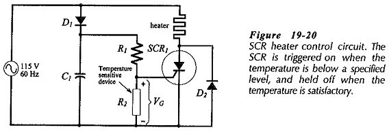
The circuit in Fig. 19-20 uses a temperature-sensitive control element (R2). The resistance of R2 decreases when the temperature increases, and increases when the temperature falls. Diode D1 keeps capacitor C1 charged to the supply voltage peak, and C1 together with resistor R1 behaves as a constant current source for R2. When R2 is raised to the desired temperature, VG drops to a level that keeps the SCR from triggering. When the temperature drops, the resistance of R2 increases, causing VG to increase to the SCR Applications Circuits triggering level. The result is that the load power is turned off when the desired temperature is reached, and turned on again when the temperature falls to a predetermined level. Rectifier D2 might be included, as illustrated, to pass the negative half-cycle of the supply waveform to the load.