Static Distance Protection Relay:
Static Distance Protection Relay are characterized by having two input quantities respectively proportional to the voltage and current at a particular point in the power system, referred to as the relaying point. The ideal forms of such relays have characteristics which are not dependent on the actual values of voltage and current, but only on their ratio and the phase angle between them. The basic measurement of impedance is done in comparators of the type already discussed which pass on the signal to tripping circuit through suitable timing unit.
Typical Distance Relay Characteristics:
A schematic block diagram showing the general scheme to get a characteristic equation which directly fits any sort of relay is shown in Fig. (12.19). Voltage VL and current IL are fed into measuring circuit M which produce voltages:
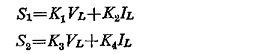
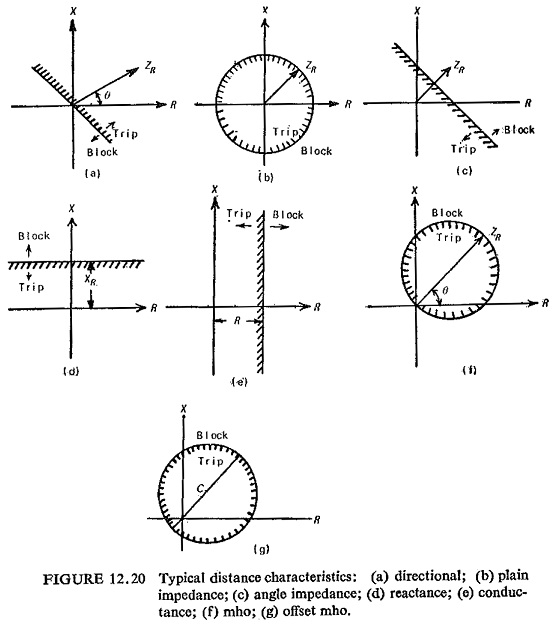
These voltages are then fed to a comparator C (amplitude or phase) so as to produce a desired pickup characteristic, the constants of K1 through K4 being selected accordingly. Typical distance characteristics are shown in Fig. (12.20) on the complex plane. For these characteristics Table 12.1 lists derived voltages S1 and S2 both for amplitude and phase comparators.
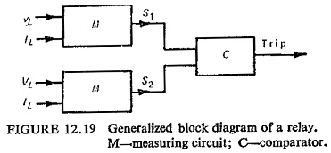
The polar characteristic of a Static Distance Protection Relay defines the range of impedance values of the protected primary circuit for which the relay gives circuit breaker tripping, whilst beyond this range, the relay remains inoperative.
In this way the polar characteristic of the relay provides its main discriminative features, and the underlying basis on which Static Distance Protection Relay is applied is that of matching the polar characteristic to the anticipated range of primary-circuit fault conditions.
As already discussed a large range of Static Distance Protection Relay schemes are possible, which differ basically in speed of operation, characteristic of measuring unit and the type of fault covered. Directional reactance and the mho-scheme for distance protection are discussed here.
Directional Reactance Scheme: Figure (12.21) represents the block schematic of this scheme. The reactance relay provides the main forward-reach characteristic in the first and second zones, and the characteristic derived from the mho relay is added to this in order to avoid operation of the protection under ordinary loading conditions and to give directional discrimination at the relay location. A tripping output is derived only when both relays operate simultaneously and the resultant characteristic of the combination is then that area in the impedance axis that is common to the individual relay characteristics. Both mho and reactance relays give initial high-speed relaying, and then after a preset time delay the setting of the reactance relay is increased to give the zone 2 value and finally the mho relay trips on its own in zone 3 after the zone 3 time delay has elapsed.
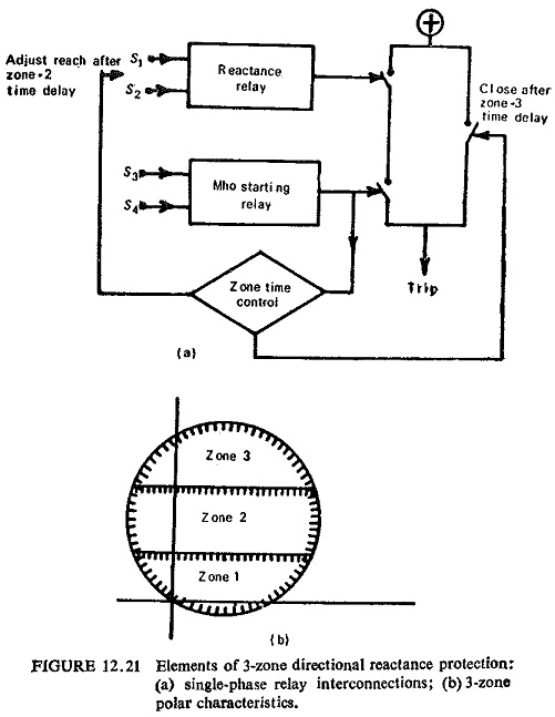
Of particular importance to the correct operation of the scheme is the time coordination between the reactance and starting relays. If for example, a fault initially covered by the zone 3 characteristic, which prepares the protection to trip after the appropriate time delay, is then cleared from another location, and the system is consequently returned to healthy load conditions which correspond to a point in the impedance plane outside zone 3 but below the zone 1 reactance setting, clearly the zone 3 relay should reset before the zone 1 relay is permitted to measure.
The interconnection of the relays is shown in Fig. (12.22a). The zone 1 relay trips directly through contacts A, and the reach of this relay is increased after the zone 2 time delay. As in the directional-reactance scheme, the zone 3 characteristic initiates the zone time control, from which the zone 1 reach is switched to zone 2, and the zone 3 relay then trips through contacts B after the zone 3 time delay.
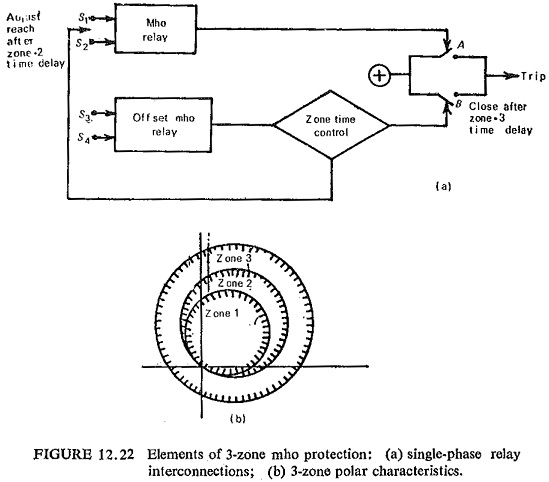
As each characteristic is derived from only one relay, the time coordination of the two relays that is required in directional-reactance scheme does not arise. However, the scheme may require reexamination in relation to its application to primary transmission circuits having high power ratings, where the low impedance levels encountered under heavy load conditions may encroach upon the zone characteristics, particularly that in zone 3, and the protection may become more prone to incorrect tripping on fault recovery when synchronous plant is in an oscillatory mode of operation.
Complete Relay Interconnections:
The combinations of relays shown in Figs. (12.21) and (12.22) may be repeated for each phase of the protected circuit for earth-fault protection, and a separate group of relays may be used for phased-fault protection to give a complete scheme. Some economy in relays may be achieved by switching relaying signals to fewer relays, according to the type of fault and the phase or phases involved.
Special Characteristics:
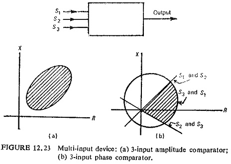
Distance relay characteristics discussed so far are either straight lines or circular on the complex plane. Other figures or combination of straight lines and circle are also possible to achieve as operating characteristics. An example of this is shown in Fig. (12.23). Many special impedance characteristics have resulted, because of the limitations of the characteristics of Static Distance Protection Relay already studied, for long lines which are heavily loaded and are operating at or near the stability limit, these may cause incorrect operation because they may fail to distinguish between power swings and faults. Some of the best known special characteristics are the swivelling characteristic, the conic section characteristic and the quadrilateral characteristic.
(a) The Swivelling Characteristic: The suitability of relay characteristics for the protection of transmission line depends on the nature of the line or the ratio ZS/ZL. For low ZS/ZL, ratio, the impedance characteristics of the relay should be the circle and for high ZS/ZL ratio it should be a straight line. It would therefore be most desirable if the characteristics could be varied to suit the length of the line or ZS/ZL ratio. This is possible with the help of a polarized mho relay.
The polarized mho relay has an offset characteristic, in the case of unbalanced faults, which encloses the origin and hence enhances the relay reach in the direction of resistance axis. The degree of offset is a function of ZS/ZL.
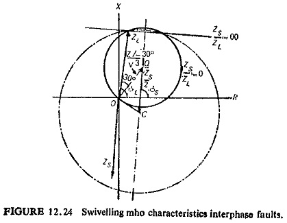
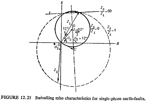
Figure (12.24) shows the swivelling mho characteristic for interphase faults. Swivelling is not so effective with single phase ground faults, because the ZS/ZL ratio can be reduced by high ground resistance and there would be a tendency towards the mho characteristic just when the reactance characteristic is essential. Figure (12.25) illustrates swivelling mho characteristic for single-phase ground faults.
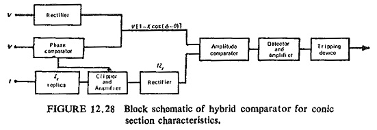
(b) Conic Section Characteristics: Many of the limitations of the conventional distance relay characteristics are overcome by the use of other conic characteristics such as ellipses, parabolas, etc. This characteristic can be achieved by a three-input amplitude comparator or by hybrid comparator (combination of phase and amplitude comparator). The basic circuit for three-input amplitude comparator is shown in Fig. (12.26).
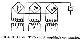
The three inputs A, B and C are:
where
Vr = fault voltage at the relay point
Z1 and Z2 = replica impedances
I = fault current
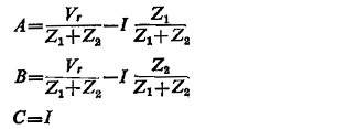
If Z1 and Z2 represent the vectors the tips of which coincide with the foci of the ellipse drawn on complex plane, and if 2a represents the major axis of ellipse then
![]()
where ZL is the line impedance.
If the characteristic is passing through origin as in Fig. (12.27) then
![]()
Multiplying Eq. (12.15) by I
![]()
Putting IZL = Vr, we can write
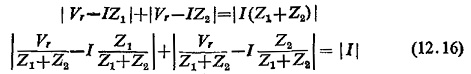
Equation (12.16) represents the operating characteristics of such a relay. In the case of a hybrid comparator the general equation for a conic section is
![]()
Equation (12.17) represents an ellipse if K<1, a parabola if K=1, a hyperbola if K>1 and a circle if K=0.
The inputs necessary for obtaining the elliptical characteristic of Eq. (12.17) are IZr, V and KV cos (Φ – θ). The first two inputs are fed directly to the amplitude comparator but the cosine term is obtained from an auxiliary phase comparator which uses the voltage IZr to polarize the line voltage V. The block schematic for this is shown in Fig. (12.28).
(c) Quadrilateral Characteristics: It is possible to get this characteristic with four relays having straight line characteristic. The static arrangement for such a characteristic is very flexible and is easily realizable in two ways : (i) combination of two phase comparators and (ii) multi-input comparator.
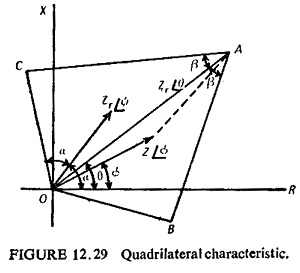
Combination of two-phase comparators: The quadrilateral characteristic is obtained by two restricted directional units, one offset from the origin by the replica impedance Zr. The relay trips if the impedance Z seen by the relay lies between the two relay characteristic, i.e. within the area OBAC (Fig. (12.29)). Hence Z must be between OB and OC and Z—Zr must be between AB and AC. Such a comparator is not entirely free from transient overreach for faults occurring at voltage zero because Zr is not a true replica impedance of the line. However this is not serious.
Four-input phase comparator: The difficulty with the two comparators being used each with two-input is that the output of each comparator has to be prolonged for a short time because they may not occur at the same time. This results in wrong tripping. The single multi-input comparator avoids this trouble without loss of time. It trips immediately when all the conditions are satisfied simultaneously.
The four inputs required for a quadrilaterial characteristics are
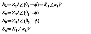
To enclose the fault area:
![]()
This gives a composite impedance characteristic as shown in Fig. (12.30). The mho circle caused by the intersection of S1 and S2 will not interfere with the rectangular tripping area if Zr = Rr + jXr because the circle of diameter Zr goes through the corners of the rectangle bounded by Rr and Xr. Tripping, occurs if all the equations resulting from comparison of all the inputs in pairs are simultaneously satisfied for the length of time set by the delay unit.
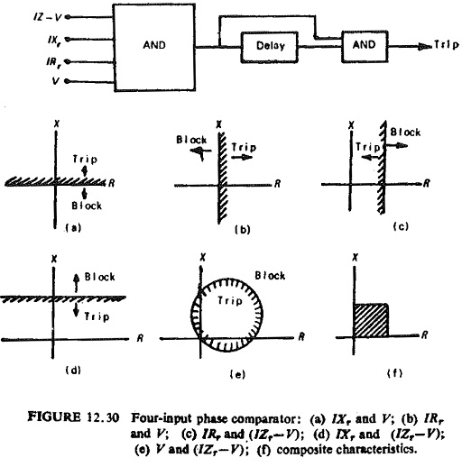
The unwanted mho circle resulting from the interaction of V and (IZr – V) can be eliminated by making at least one of them a pulse. A quadrilaterial can be obtained by using a multi-input sine comparator with the following inputs:
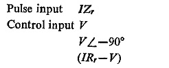
Tripping occurs if the IZr pulse occurs during the coincidence period of the three sinusoidal inputs. It can easily be seen that this occurs only for an internal fault.