Overcurrent Relay Characteristics:
The operating time of all Overcurrent Relay Characteristics tends to become asymptotic to a definite minimum value with increase in the value of current. This is inherent in electromagnetic relays due to saturation of the magnetic circuit. So by varying the point of saturation different Overcurrent Relay Characteristics are obtained; these are:
- Definite time.
- Inverse definite minimum time (IDMT).
- Very inverse.
- Extremely inverse.
These Overcurrent Relay Characteristics are obtained by induction disc and induction cup relays.
The torque of these relays as shown earlier is proportional to Φ1Φ2 sin α where Φ1 and Φ2 are the two fluxes cutting the disc or cup and α is the angle between them. Where both fluxes are produced by the same quantity, as in current or voltage operated relays, then below saturation the torque is proportional to I2, the coil current, or T = KI2. If the core is made to saturate at a very early stage with the result that by increasing I, K decreases so that the time of operation remains same over the working range. The characteristic is shown by curve (a) in Fig. (4.6) and is known as definite time.
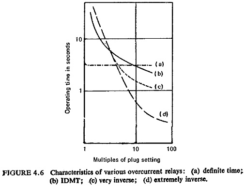
Now if the core is made to saturate at a later stage, the characteristics assume the shape shown by curve (b) Fig. (4.6) known as IDMT. The time-current characteristic is inverse over some range and then after saturation assumes the definite time form. At low values of operating current the shape of the curve is determined by the effect of,the restraining force of the control spring, while at high values the effect of saturation predominates.
Different time multiplier setting (TMS) are obtained by varying the travel of the disc or cup required to close the contacts. The higher the time multiplier setting, the greater will be the spring restraining force. In order to make the relay operate at a constant value of minimum trip current for any TMS, graded holes are cut in the disc or a disc with spiral cut edge is used. Thus, as the disc moves in the tripping direction, winding up the spring, more and more conducting metal of the disc comes into play in the active air gap of the electromagnet to increase the electric torque, thus compensating the increasing spring torque.
If the saturation occurs at a still later stage the characteristics assume the shape shown by curve (c) in Fig. (4.6) known as very inverse. The time-current characteristics is inverse over a greater range and after saturation tend to definite time.
The curve (d) in Fig. (4.6) shows extremely inverse characteristics, i.e. the saturation occurs at a very late stage and the equation of the curve is roughly of the form I2 t = K where I is the operating current and t is the time of operation.
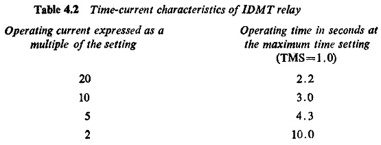
Out of all these characteristics IDMT is the only characteristic which is specified by Indian Standards (IS: 3231-1965) the rest are all relative curves. Table 4.2 shows the time-current characteristics of an IDMT relay.
The time-current characteristic is conveniently plotted on a log-log scale. Figure (4.7) shows the IDMT characteristics with different time multiplier settings (TMS).
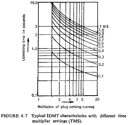
Theoretically their time ordinates should be proportional to the time multiplier setting so that, if the times for a given current were divided by the TMS all the curves should coincide. Owing to the inertia of the disc which takes a little time for the disc to accelerate from standstill to its steady speed at low current values they may not exactly coincide. It introduces. some error in time which might affect the discrimination of the whole scheme.. The errors permissible as per IS: 3231-1965 are shown in Fig. (4.8).
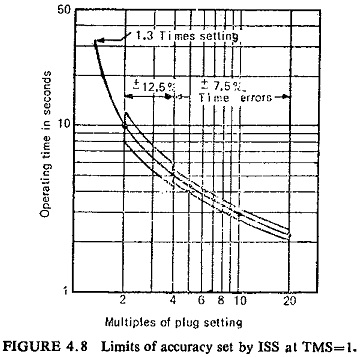
At any other time setting, and with a current equal to 10 times the prescribed current setting, the relay shall conform to accuracy class 7.5 in respect of its operating time. However, if the error corresponding to the accuracy class does not exceed 0.1 second, the latter may be taken as the permissible error.
At any other current setting, and with a current equal to 10 times the current setting, the setting of time multiplier being the highest (TMS=1), the relay shall conform to accuracy class 10 in respect of its operating time.
The relays shall not operate at a current equal to or less than the setting; the minimum operating current shall not exceed 130% of the setting.