Overcurrent Earth Fault Protection:
Overcurrent Earth Fault Protection – Earth-fault protection can be provided with normal overcurrent relays, if the minimum earth-fault current is sufficient in magnitude. The magnitude of earth-fault current is usually low compared to the phase-fault currents because the fault impedance is much higher for earth-faults than for phase-faults. It also depends On the type of neutral earthing, i.e. whether solidly earthed, insulated or earthed through some resistance or reactance. Whatever the case may be the earth-fault current will be small compared to the phase-fault currents in magnitude.
The relay thus connected for earth-fault protection is different from the ones provided for phase-faults. It has the peculiarity that it is set independent of load current and thus settings below normal load current can be achieved. Hence earth-fault relays are set at low settings between 30% and 70% but low values of current settings impose a higher burden on the relay with rated current in the primary of the CT. It will be seen that unless the earth-fault current is limited or special CTs are used to provide a higher output, time/current grading of earth-fault relays is not practicable.
Fortunately the grading of earth-fault relays, unlike overcurrent phase relays, is normally limited to one system voltage due to general use of delta/star step down transformer, as the earth-fault in one section does not draw ground current from other parts. This simply means that an earth-fault on one side of the transformer will not be seen by the earth-fault relays on the other side and hence the grading between the relays on the different voltage systems is not required.
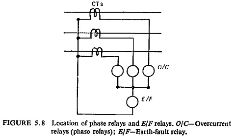
Overcurrent Earth Fault Protection can be provided with only one overcurrent relay connected in the residual circuit or across the zero phase sequence filter. A current will flow through the relay winding only when a fault involving earth occurs. Figure (5.8) shows the location of the earth-fault relay along with the phase relays.
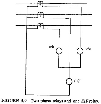
When both overcurrent and earth-fault protection are required using IDMT relays it is usual to provide two phase relays instead of three phase relays with one earth-fault relay from economic considerations (Fig. (5.9)).
If all the CTs were ideal, under normal operating conditions and interphase faults no current would flow through the earth-fault relay. However, when commercially identical CTs are used some current would flow through the relay. This is due to difference in errors and in amounts of residual magnetism. This current is called unbalance current or false residual current which is in the range of 0.01 to 0.1A at rated primary current and many times larger when heavy phase-fault currents flow.
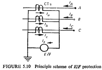
Figure (5.10) illustrates the principle of earth-fault protection. Obviously during normal operation and also for three-phase and line-to-line faults, the current passing through the relay is equal to zero:
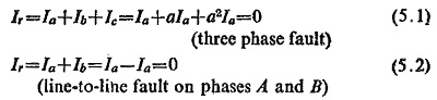
When a single or double earth-fault occurs, the zero sequence current flows through the relay. Now from the equivalent circuit of the CT we have
![]()
where
Is = secondary current
I′p = primary current referred to secondary
I′e = exciting current referred to secondary
Ip = primary current
Ie = exciting current
n=secondary to primary turn ratio
Accordingly we can write
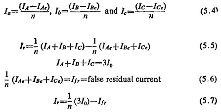
Equation (5.7) shows that earth-fault relay responds to zero sequence current and the value of the pickup of earth-fault relay has to be selected against the maximum value of false residual current only.