Directional Earth Fault Relay:
In the case of Directional Earth Fault Relay the angular relationship of residual current and residual voltage is independent of the faulted phase and is governed only by the R/X ratio of the fault path. The current coil of the directional element is connected to detect current in the residual circuit of the CTs and the voltage coil is connected to a suitable voltage source to give sufficient torque. Thus for a residual current Ir and residual voltage Vr the torque will be proportional to IrVr cos (Φ-θ) where θ is the maximum torque angle of the relay and Φ is the angle between applied voltage and current.
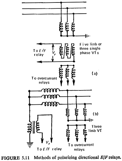
The residual current as shown earlier is obtained with the help of three CTs. A common arrangement for obtaining residual voltage employs a five-limb voltage transformer or its equivalent with a star-connected primary, the star point being earthed, and an open delta secondary. The voltage across the open delta is applied to the voltage coil of the directional element of the relay. This is illustrated in Fig. (5.11a).
Another method of obtaining residual voltage is shown in Fig. (5.11b) for systems earthed through arc-suppression coil. The voltage which appears across the arc-suppression coil is applied to Directional Earth Fault Relay.
The magnitude of Vr when a fault occurs depends on the method of earthing the system neutral, and the fault resistance. An earth fault causes the system neutral to shift in case of systems earthed through some impedance. It can be shown that:
- The higher the earthing impedance, the higher is the residual voltage (tending to a value of three times phase voltage), and if this impedance is resistive the power factor is high. Fault resistance has negligible effect on the residual voltage. (Although the current is low, which can be compensated for by using a sensitive relay, all other factors are favourable for high torque in the relay.)
- With low impedance or solidly earthed systems the residual voltage does not exceed nominal phase voltage. As the fault-loop impedance is mainly reactive, the power factor is very low. Fault-arc resistance obviously gives some improvement in power factor, but reduces the residual voltage further. (Fault current is high, but all other factors are contrary to the production of high torque in the relay.)
A resistance earthed system provides the most satisfactory conditions for relay operation. It facilitates the tripping of the faulted circuit without undue delay (i.e. within a few seconds).
For low-impedance or solidly earthed systems the relays are designed to operate with low residual voltages. The production of full flux at very low voltage may give excessive saturation of the voltage-coil core at nominal voltage, leading to over loading of the VT. This is a major design consideration.
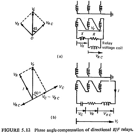
Another consideration with the solidly earthed system is the low fault power factor. For this some phase angle compensation can be applied. Two such phase angle compensation methods are shown in Fig. (5.12).
The first method is illustrated in Fig. (5.12a). The two equal impedances—one resistive and the other reactive—are connected across the residual voltage, whereas the voltage coil of the earth-fault relay is connected across the resistive impedance. Thus the voltage across the resistor and the relay coil in parallel (VRC) lags the residual voltage Vr by approximately 45°. By doing this the torque increases even at low fault power factors. For example, with a fault power factor of unity, the fault current IF leads the voltage across the relay coil VRC by approximately 45°, and the expression for torque is approximately equal to 0.7 IF VRC. Now with a fault power factor of 0.7 lagging, IF is in phase with VRC, and the torque becomes IF VRC or 1.4 times torque for a unity power factor fault. If the relay already has a 15° compensation angle the relay torque will be a maximum for a fault power factor of 0.5 lagging.
The second method is illustrated in Fig. (5.12b). It can be seen that the relay coil voltage can be arranged to lead the residual voltage by 120° and the required lag of 60° is obtained by reversing the coil connections.
Earth-Fault Detection in Systems Earthed through Arc Suppression Coil. In a system earthed through a continuously rated arc suppression coil, the earth-fault is detected by energising a relay either from the secondary winding of the coil or from a low-ratio CT in the neutral-earth connection. Figure (5.13) represents a simple three-phase system earthed through an arc-suppression coil for a fault on phase A. The relay torque is proportional to VrIr sin α.
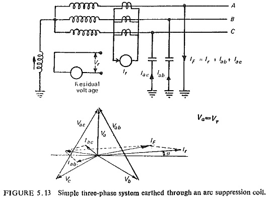
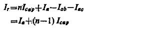
In case of multi-feeder system it is necessary to detect as to which circuit is faulted. A supersensitive Directional Earth Fault Relay is used on each feeder. Consider a case of n feeders each provided with a sensitive earth-fault relay of the type shown above. It can be seen that the relays on the healthy circuits restrain and the relay on the faulted circuit operates. No capacitive current flows in phase A of any healthy feeder since this phase is at earth potential. Figure (5.14) illustrates one such system. Assuming that the circuits have equal capacitances and resistances, the total capacitive current per feeder is
![]()
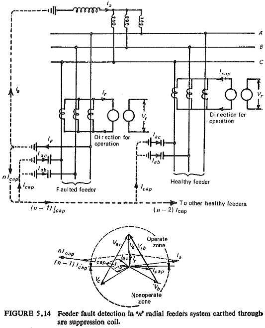
and the total capacitive current of the system under fault conditions nIcap. Assuming the direction of flow away from the busbars as the positive direction a current of nIcap flows in phase A of the faulted feeder. Then the residual current in the faulted feeder is given by