Single Phase Directional Relay:
Single Phase Directional Relay – The general Eq. (4.8) suggests that for directional control the individual torques, viz. K |A|2 and K′ |B|2 should be eliminated.
![]()
Considering a voltage current directional relay the general Eq. (4.8) reduces to
![]()
The spring constant K” has no function and can be reduced to zero, so
The directional characteristic when plotted is shown in Fig. (4.12) which shows that the maximum torque occurs when θ = Φ. In a voltage current directional relay, θ will not be 90° because of the impedance angle
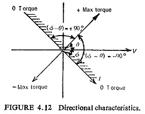
of the potential coil. If the impedance angle of the potential coil is λ, then θ = 90-λ. This is shown in Fig. (4.13), where ΦI and ΦV are two fluxes produced by current coil and pressure coil. Maximum torque is
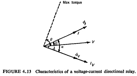
produced when angle α between two fluxes is 90°, i.e. when θ = Φ or
This suggests that external phase shifting circuits can be used to change the value of θ.
The characteristics of such a Single Phase Directional Relay is shown in Fig. (4.14).
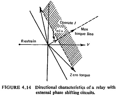
Maximum torque position can be changed by inserting resistance or capacitance or a combination of the two in series with the voltage circuit. Each value of polarizing (i.e. reference) voltage will have a constant torque line. Because of the control spring force and friction, there is a minimum value of current Imin required to operate the relay.