Power Measurement in Single Phase Circuit by Wattmeter:
Wattmeters are generally used to measure power in the circuits. A wattmeter principally consists of two coils, one coil is called the current coil, and the other the pressure or voltage coil. A diagrammatic representation of a wattmeter connected to measure power in a single phase circuit is shown in Fig. 9.42.
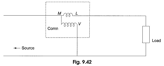
The coil represented with less number of turns between M and L is the current coil, which carries the current in the load and has very low impedance. The coil with more number of turns between the common terminal (comn) and V is the pressure coil, which is connected across the load and has high impedance.
The load voltage is impressed across the pressure coil. The terminal M denotes the mains side, L denotes load side, common denotes the common point of current coil and pressure coil, and V denotes the second terminal of the pressure coil, usually selected as per the range of the load voltage in the circuit. From the figure, it is clear that a wattmeter has four terminals, two for current coil and two for potential coil. When the current flow through the two coils, they set up magnetic fields in space.
An electromagnetic torque is produced by the interaction of the two magnetic fields. Under the influence of the torque, one of the coils (which is movable) moves on a calibrated scale against the action of a spring. The instantaneous torque produced by electromagnetic action is proportional to the product of the instantaneous values of the currents in the two coils. The small current in the pressure coil is equal to the input voltage divided by the impedance of the pressure coil. The inertia of the moving system does not permit it to follow the instantaneous fluctuations in torque.
The wattmeter deflection is therefore, proportional to the average power (VI cos Φ) delivered to the circuit. Sometimes, a wattmeter connected in the circuit to measure power gives downscale reading or backward deflection. This is due to improper connection of the current coil and pressure coil.
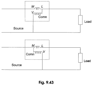
To obtain up scale reading, the terminal marked as ‘Comn’ of the pressure coil is connected to one of the terminals of the current coil in Single Phase Circuit as shown in Fig. 9.43. Note that the connection between the current coil terminal and pressure coil terminal is not inherent, but has to be made externally. Even with proper connections, sometimes the wattmeter will give downscale reading whenever the phase angle between the voltage across the pressure coil and the current through the current Source coil is more than 90°. In such a case, connection of either the current coil or the pressure coil must be reversed.