Measurement of Electrical Quantities:
Measurement of electrical quantities which includes
- Measurement of Voltage
- Measurement of Current
- Frequency Measurement
- Phase-Angle Measurement
- Power-Factor Measurement
- Impedance Measurement
- VA Measurement
- Power Measurement
- VAR Measurement
- Energy Measurement
Measurement of Voltage
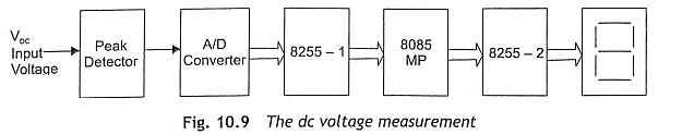
Figure 10.9 shows the schematic block diagram of dc voltage measurement. Firstly, the dc voltage is applied to the peak detector circuit to detect the peak value of dc voltage when the dc voltage varies instantaneously. Usually, the average and rms values of input voltage are directly proportional to peak of dc voltage.
The peak detector circuit is depicted in Fig. 10.10.
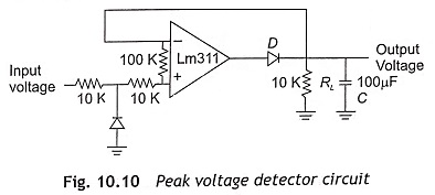
When input voltage is positive, output of the operational amplifier drives the diode D, and the capacitor C will be charged to the positive peak value of dc input voltage. In this circuit, when the diode D is forward bias, operational amplifier operates as a voltage follower. If input voltage becomes negative, the diode D is reverse biased and voltage across the capacitor C will be retained as the capacitor discharges through resistance RL only. For satisfactory operation of peak detector circuit, the charging and discharging time constant must follow the given condition.
CRD ≤ CRL
where,
- CRD – charging time constant,
- CRL – discharging time constant,
- RD – resistance of forward bias diode,
- RL – load resistance
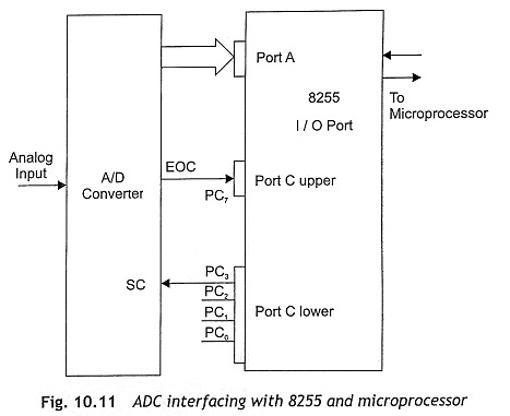
The output of the peak detector circuit is fed to the A/D converter. Subsequently, analog dc voltage is applied to the analog input terminal of the A/D converter. The output of the A/D converter is digital equivalent to the analog input voltage. The outputs of the A/D converter are connected to the I/O ports of 8255 and the microprocessor can read this digital output of ADC through 8255 and transfer the digital data to the accumulator. ADC interfacing with 8255 and the microprocessor is illustrated in Fig. 10.11.
In this Measurement of Electrical Quantities section, the program for dc voltage measurement in the range of 0 to 5 V has been incorporated and displayed in the mV range. Therefore, 0000 will be displayed for 0 V and similarly 5000 will be displayed at 5 V dc input voltage. While writing the program, the given steps are followed for dc voltage measurement:
- Convert analog input voltage into digital form and store in memory location
- Find the memory location of the look-up table where the calibrated data of digital equivalent voltage is stored. The address is calculated from the following expressions. Actual address = Hex code of analog input voltage x 2 + Initial address
- Call data stored in the two consecutive memory locations and display in the address field of the microprocessor kit or in the seven-segment display.
To measure 0 to 5 V dc, the A/D converter IC operates in unipolar mode and the digital equivalent value of 0-5 V will be 00H to 80H. 00H is equivalent to 0 V and 80 is equivalent to 5 V. When an analog input voltage is converted to a digital equivalent by the A/D converter then the microprocessor reads a digital equivalent voltage. The look-up table or multiplication factor will be used for calibration of digital equivalent voltage to display. The resolution of 8-bit 0-5 V ADC is 20 mV. Then relationship between analog input voltage and hex output is
![]()
where,
- X is the decimal equivalent of a hex number.
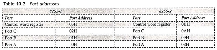
Two I/O ports, 8255-1 and 8255-2, are used for measurement of dc voltage. Port A and Port C of 8255-1 are used for ADC interfacing, and Port A and Port B of 8255-2 are used for display interface. Assume Port A, and Port C upper of 8255-1 operate as input ports, and Port B and Port C lower as output ports. It is also assumed that all ports of 8255-2 operate as output ports. The control word of 8255-1 is 98H and the control word of 8255-2 is 80H. Assume the following port addresses of 8255-1 and 8255-2 as shown in Table 10.2.
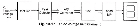
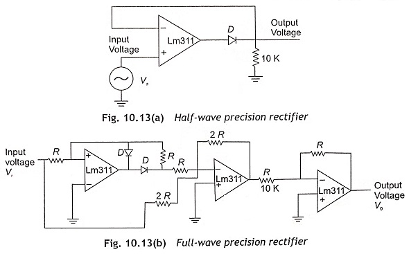
The schematic block diagram of ac voltage measurement (peak value) is illustrated in Fig. 10.12. A rectifier is used to convert ac voltage into dc voltage. Therefore, rectifier output is a dc voltage source, which can be represented as constant voltage source in series with a resistance. In a microprocessor-based system, it is necessary to rectify millivolt high-frequency signal. When conventional diodes are used in a rectifier circuit, there is always some voltage drop across forward bias diode 0.2 V for Ge diode and 0.7 V for Si diode, so that a milivolt signal cannot be able to forward bias the conventional diode. The switching speed of a conventional diode is also low. If a diode is used in the forward path of an operational amplifier, cut-in-voltage of diode will be divided by the open-loop gain, which is very large in an operational amplifier. Then the diode can operate in ideal mode with zero cut-in voltage. If a conventional diode is used in feedback path of operational amplifier, high-frequency milivolt can be rectified. This rectifier is known as precision rectifier. There are two types of precision rectifiers such as half-wave rectifier and full-wave rectifier. Figure 10.13 shows the half-wave and full-wave precision rectifiers.
The magnitude of ac voltage changes with time. So a sample hold circuit is required to maintain analog voltage during the A/D conversion process. A bi-directional A/D converter must be used to measure positive as well as negative voltage to display the instantaneous value of analog ac voltage. To measure the average as well as rms value of ac voltage, a precision rectifier is used to convert ac voltage to dc. Then measure the dc voltage with the help of an A/D converter, 8255 and microprocessor and after proper calibration it will be displayed in the address field of the microprocessor or in the seven-segment display.
A similar process will be followed for writing program to measure the ac voltage. To measure high voltage, a Potential Transformer (PT) is required. The primary of PT is connected to high-voltage supply and the output from PT secondary winding is fed to precision rectifier.
Measurement of Current
In this Measurement of Electrical Quantities, firstly the current must be converted into voltage using I to V converter and then voltage is measured by the microprocessor with the help of an A/D converter and 8255 programmable peripheral interface IC. Figure 10.14 shows the dc current-to-voltage converter circuit. Current flow through the RS resistance is zero as operational amplifier is virtually grounded. Therefore, I2 current flows through resistance R2 and output voltage is equal to V0 = -I2R2. The ac current-to-voltage converter circuit using Current Transformer (CT) and operational amplifier is depicted in Fig. 10.15. If output voltage at secondary of CT is V1, output voltage will be equal to V0 = – R2/R1 V1.
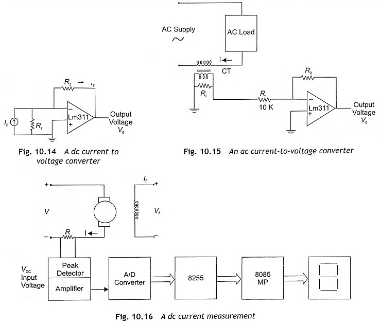
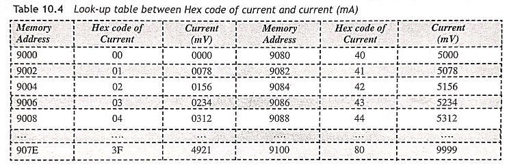
Figure 10.16 shows the current measurement of a dc motor. For the measurement of current, the current signal is converted to voltage signal. A very low resistance of approximately 0.1 ohms may be connected in series with the load. Then voltage across the resistance should be equal to 0.1 times of load current (I). After amplifying by ten times, the amplifier output voltage must be equal to the current. Then output analog voltage is applied to the input of the peak detector circuit so that it can deliver 5 volts when 5 A current flows though the circuit. Thereafter, by measuring voltage, we can measure analog input current in digital form. The program for voltage measurement may be used in current measurement also. But there will be some changes in the look-up table. In the look-up table for each digital input signal due to corresponding input, current calibrated data must be stored in two successive memory locations as given in Table 10.4.
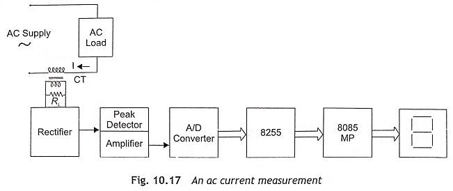
In ac current measurement, a Current Transformer (CT) may replace the sensor resistance. The current transformer (CT) or a core-balanced transformer should be connected with a burden as depicted in Fig. 10.17. The output signal in the voltage drop across the secondary of CT or burden resistance is applied to an A/D converter through precision rectifier and peak detector circuit. Then the microprocessor measures analog voltage and displays it in seven-segment display units.
For dc current measurement, assume R = 0.1 Ω and maximum current I = 5 A. Then IR drop = 0.5 V. If an amplifier is used to increase voltage with a gain = 10, output voltage will be 5 V. Subsequently, the look-up table for voltage measurement can be used and current displayed in mill-amperes.
In ac current measurement assume CT ratio = 10 : 1, and primary current IP = 10 A. Then current flow through secondary IS = 1 A, and voltage across resistance VR = 0.1 V. Two amplifiers circuits will be used to produce 5 V output. Gain of the first-stage amplifier is 10 and the second-stage amplifier gain is 5. Here full-scale analog voltage is 5 V for 10 A current and its digital equivalent output is 80H. The program for voltage can be used in this case but the look-up table must be modified. The modified look-up table is given below:
Frequency Measurement
To measure the frequency of an ac signal, firstly the ac signal is converted into dc square waveform using Zero Crossing Detectors (ZCD) as shown in Fig. 10.18. Then the time period of half cycle of square wave is measured, which is directly related with frequency. The relation between frequency (f) and time period (T) is f = 1/T.
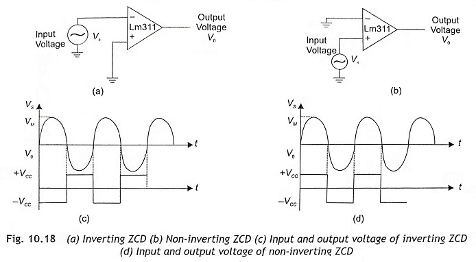
Usually, the Zero Crossing Detector (ZCD) is an open-loop or saturation-mode operation of the operational amplifier and it is basically a comparator with zero reference voltage. Zero crossing detectors are of two types—inverting and non-inverting type as shown in Fig. 10.18 (a) and (b) respectively. Whenever the input voltage crosses the zero axis, the output voltage changes abruptly. In an inverting zero crossing detector, input voltage is applied to the inverting terminal, and the output voltage signal is out of phase (180 phase shift from the input voltage). In case of non-inverting zero crossing detector, the input voltage is applied to the non-inverting terminal. Therefore, the output voltage is in phase with the input signal.
As depicted in Fig. 10.18(b), ZCD converts the positive half-cycle of ac input voltage to a rectangular waveform. Output is low in the negative half-cycle and high in the positive half-cycle. The amplitude of a square wave will be either +VCC or –VCC. When the operational amplifier operates in +12 V and –12 V, the output voltage will vary in between +12 V and 2 V. But microprocessors can operate at 5 V only. Therefore, the output square wave must be converted into +5 V and 0 V using some additional arrangement in ZCD as depicted in Fig. 10.19.
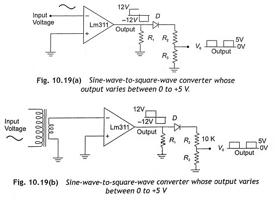
A sinusoidal signal is converted to square wave using a voltage comparator LM 311 or operational amplifier LM 747 or LM 324 as shown in Fig. 10.19. A diode is used to rectify the output signal. A potential divider is used to reduce the magnitude to 5 volts. The microprocessor receives the output signal of ZCD through I/O ports of 8255 to detect the rising edge and falling edge of square waveform using an assembly-language program. The program for zero crossing detectors to detect rising edge and falling edge of a square waveform is given below.
The above program has been written to detect the rising and falling edges of a square waveform. Increment BC register pair, after detecting rising edge and increment DE register pair after detecting falling edge.
Initially, assume Port A as input and Port B and Port C as output ports. Find the control word of 8255 and load it into control word register. The ZCD output is connected to the PA0 of 8255. The PA0 pin will be either low or high. If it is high, it waits till the signal becomes low. As soon as it receives the low signal, the counter DE register pair will be incremented. When the signal is low, it waits till the signal becomes high. After that, the counter BC register pair will be incremented.
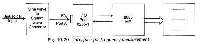
Figure 10.20 shows the schematic block diagram of frequency measurement, which consists of a step-down transformer, a Zero Crossing Detector (ZCD), 8255 PPI and 8085 microprocessor. The step-down transformer changes the supply voltage to 5 V signal and fed to a ZCD. The output of ZCD is a 5 V square wave, which is connected with the PA0 of 8255 PPI.
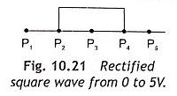
The microprocessor checks the status of PA0 pin of 8255. At point P1 ,the PA0 = 0. PA0= 1 at point P2. As soon as P2 becomes 1 and PA0 status has been changed from 0 to 1, the counter starts counting but the microprocessor checks the status of PA0 continuously as the counter should count until PA0 changes from 1 to 0. At point P4, PA0 becomes 0 from 1 and the processor terminates the counting process. In this way, half-cycle time is measured in terms of count value, which is stored in the BC register pair. A look-up table will be stored into a microprocessor for conversion from the count value of time period to frequency. Actually, the hexadecimal count value is compared with a look-up table and frequency will be measured and displayed in data field or address field of microprocessor or in the seven-segment display units.
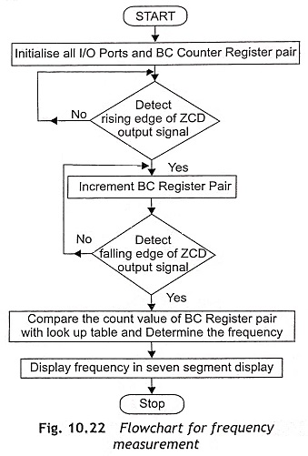
In the above program, instructions from memory location 8007H to 800CH can be used to check whether the level of ZCD output is 0 or 1. If it is in level high or ‘1’, again execute instructions from memory location 8007 H to 800C H. Otherwise, start execution from 800E H memory location. Instructions are written in between 800E H and 8013 H to detect the rising edge of ZCD output (square wave signal). As soon as the rising edge is detected, the counter starts counting and again reads PA0 to check the status of ZCD output. Here, the BC register pair is used as a counter and it counts continuously until falling edge of ZCD output square wave is detected. Parts of the main program from memory location 8015H to 801BH are used for this purpose. In this way, the time period for half cycle is measured in terms of count value. The count value is inversely proportional to the frequency. When the count value is low, the frequency will be high and vice versa. The count value can be converted into frequency by computation or by using a look-up table. The flowchart for frequency measurement is depicted in Fig. 10.22.
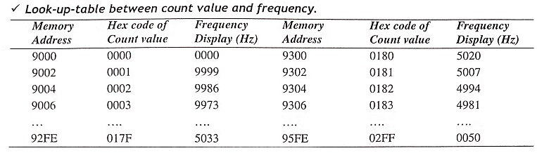
This frequency measurement program can be used to measure frequency up to 10 kHz. The look-up table between count value and frequency is given above. Here, we assume maximum count value is about 02FF and minimum count value 0000H while the program is executed. When the count value is 0001, the frequency output is 9999 Hz, which will be displayed in seven-segment display units. If the count value is 02FF, frequency output is 0050 Hz and display is in seven-segment display units.
Phase-Angle Measurement
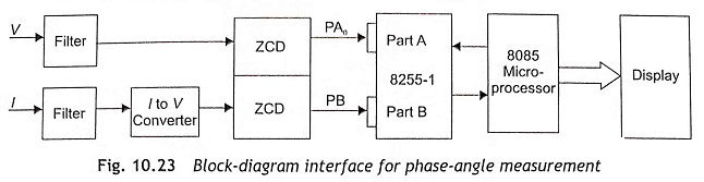
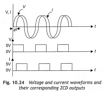
The schematic block diagram of phase-angle measurement is shown in Fig. 10.23, Assume the voltage and current waveform has a phase angle difference of Φ as depicted in Fig. 10.24. The voltage waveform converted into square waveform using ZCD. Initially, the current signal is converted into voltage signal and then voltage signal is converted into square waveform using another ZCD. The ZCD output corresponding to voltage signal is connected with PA0 of 8255 and the ZCD output due to current signal is also fed to PB7 of 8255.
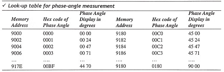
A program for phase-angle measurement should be loaded in the microprocessor. When the program is executed, the microprocessor firstly detects the instant of positive zero crossing of input voltage. Then the counter starts counting at the instant of positive zero crossing point of square wave corresponding to voltage. After that, the microprocessor checks the status of PB7 to detect the positive zero crossing point of current signal and the counter terminates counting as soon as zero crossing of the current waveform is detected. The count value of the counter is directly proportional to phase-angle difference. A look-up table, i.e., the relationship between count value and phase angle is already stored in the microprocessor. Therefore, using the said look-up table, the digital count value can be calibrated into phase angle and finally displayed in seven-segment display.
The above program for frequency measurement is written by using the following steps:
- Step 1 Initialization of I/O ports of 8255-1 and load 0000H in BC register to initialize counter.
- Step 2 Detect the instant of rising edge of square wave corresponding to input voltage.
- Step 3 After detecting the positive zero crossing of voltage signal, start counting, Counting will be continuing until positive zero crossing of current signal is detected.
- Step 4 Detect the rising-edge zero crossing of current wave and terminate counting. Count value will be stored in BC register pair and stored in 8100 and 8101 memory locations.
- Step 5 Call subroutine for calibration. The count value can be converted into phase angle. After that, phase can be displayed by display subroutine.
In this method, phase angle 0 to 90 degree lagging can be measured. To measure the leading phase angle, the program will be modified. Counting will be started at rising edge of a square wave corresponding to current signal and terminate counting at rising edge zero crossing of input voltage. Here, only the basic concept of phase-angle measurement has been incorporated for better understanding and program simplification.
Power-Factor Measurement
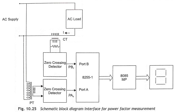
The current waveform is either lag or lead from the voltage waveform by a phase angle (Φ). The power factor is a cosine of phase angle i.e., cos Φ. Therefore, the power factor will be either lagging or leading. Figure 10.25 shows the schematic block diagram interface for frequency measurement.
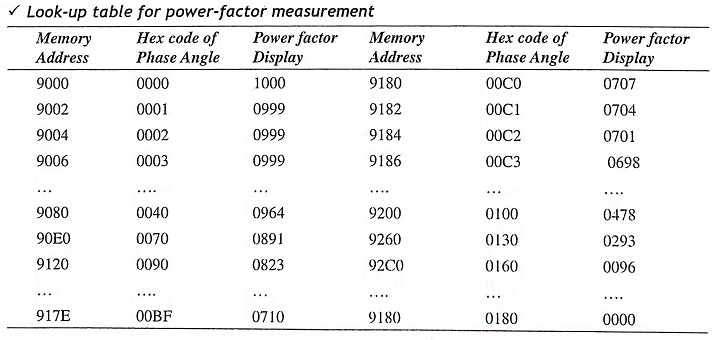
To measure the power factor, first of all phase angle is measured as explained in Section 10.3.4. After measuring phase angle, the power factor can be measured. Generally, the phase angle is well-known in terms of count value. Therefore digital value of the counter can be converted into power factor with the help of a look-up table and displayed in seven-segment display. Actually, the look-up table is the relationship between the count value and power factor and it is used for better accuracy and simplification of program. The program for phase-angle measurement can also be used in lagging power factor measurement after incorporating the new look-up table as given below. To measure the leading power factor, the same program can be used with some modification in the main program as well as the look-up table.
Impedance Measurement
In this Measurement of Electrical Quantities, Impedance of a circuit (Z) is defined as the ratio of V and I. It can he expressed by Z = V/I. To measure impedance, firstly we measure rms voltage and current using a multiplexer-based A/D converter. After measuring Vrms and Irms, the ratio Vrms/Irms can be determined by using a division subroutine. Figure 10.26 shows the schematic block diagram of impedance measurement.
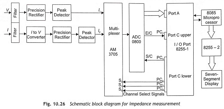
PC0, PC1 and PC2 of Port C are connected to channel select terminals of multiplexer. Input 1 of the multiplexer is connected with voltage signal and Input 2 of the multiplexer is connected with the current signal. When PC0, PC1 and PC2 are 000, Channel 1 will be selected and analog input voltage is applied to A/D converter. Start Of Conversion (SC) pin and End Of Conversion (EOC) pin of A/D converter are connected with PC3 and PC7 respectively. When the microprocessor sends SC signal to A/D converter through 8255, A/D converter starts to convert analog voltage into digital form. After that, the microprocessor reads EOC signal to detect the end of A/D conversion process. After proper A/D conversion, the microprocessor reads the digital equivalent of analog input voltage and stores the digital data in a memory location. Subsequently, the microprocessor sends PC0 = 1, PC1 = 0, and PC2 = 0 signals to select Channel 2 and analog voltage corresponding to current is fed to A/D converter. The A/D converter converts analog voltage into its digital equivalent value and stores it in the memory location. Then the microprocessor program calls a division subroutine to find the V/I ratio and displays it in the seven-segment display.
Assume dividend, i.e., digital equivalent voltage is stored in the memory location 8050H and divisor i.e. digital equivalent of current is also stored in the memory location 8051. After division, Quotient is written in 8200H and remainder in 8201H locations. In the display subroutine, the quotient will be loaded into the accumulator from 8200H and displayed as most significant digits MSDs. Similarly, the remainder can be read from memory location 8201 H and loaded into the accumulator. Then remainder is displayed as least significant digits LSDs. The program for impedance measurement is given below:
The above program for impedance measurement is written by using the following steps:
- Step 1 Initialize I/O ports of 8255.
- Step 2 Select Channel 1 and analog voltage is applied to A/D converter to convert analog voltage into digital value. Stores digital value of voltage in 8050H memory location. The part program of the above program from memory locations 8004H to 801EH is used for this purpose.
- Step 3 Select Channel 2 for current input. Convert analog equivalent voltage of current into digital value by A/D converter and store in 8051H memory location. The part program of the above program from memory locations 801FH to 8039H is used for this function.
- Step 4 Call division subroutine to determine the V/I ratio. Store the quotient in 8200H memory location and the remainder in 8201H memory locations. The division subroutine is given in the memory locations 8100H to 811FH.
- Step 5 Call display subroutine to display in seven-segment display.
VA Measurement
Figure. 10.27 shows the schematic block diagram of VA measurement. The VA can be expressed as

To measure VA, voltage V and current I are measured separately. Then the product of V and I can be computed by using a multiplication subroutine.
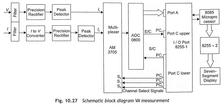
Precision rectifiers are used to convert ac voltage signals into dc voltages. The I to V converter is used to generate a voltage signal which is directly proportional to current. The output of rectifiers is fed to the peak detector circuit whose outputs are applied to a multiplexer as depicted in Fig. 10.27. Channel 1 and Channel 2 inputs of a multiplexer are V and voltage corresponding to I respectively. Then voltage and current both are converted into digital form using A/D converter and stored in memory location. Afterwards, a multiplication subroutine is called to determine the product VI. Then it is displayed in seven-segment display.
Power Measurement
To find the power consumption in a circuit, the power is calculated from the expression
P = VI cos Φ when the voltage and current waveforms are sinusoidal.
Usually, the instantaneous value of the voltage is V cos Φ when current reaches the peak. To get a pulse at the moment of peak current, a phase shifter and zero-cross detector are generally used. Firstly, the current signal is fed to the phase shifter to obtain a 90° phase shift. After that the output of the phase shifter is applied to the zero-cross detector. The instant where rising edge of square wave occurs, is the peak instant of current. The microprocessor reads the status of ZCD to detect the rising edge. As soon as the microprocessor detects the rising edge of ZCD square wave output, the microprocessor generates a sample and hold signal so that V cos Φ voltage is applied to A/D converter. At this instant, the microprocessor sends a command to the multiplexer to select Channel 1, and the instantaneous value of the voltage V cos Φ is fed to an A/D digital converter. Then the A/D converter converts V cos Φ into its digital equivalent value and stores in memory location. Afterwards, find the average value of the current using the same A/D converter and store in a memory location. Subsequently, call multiplication subroutine to determine the VI cos Φ and display the power value in a seven-segment display.
VAR Measurement
Reactive power can be expressed as
![]()
To measure the reactive power, initially V sin Φ and I are measured by microprocessor and then VI sin Φ is determined. At the instant of zero current, the instantaneous value or the voltage is V sin Φ. To detect the instant of zero current, current signal is fed to ZCD and converted into square wave. The microprocessor reads and examines the ZCD output to detect the rising edge of square wave. When the microprocessor detects the rising edge of ZCD square wave, the microprocessor generates a sample and hold signal so that V sin Φ voltage is applied to an A/D converter. At this instant the microprocessor also sends a command to the multiplexer to select Channel 2 and the instantaneous value of the voltage, V sin Φ is fed to an A/D digital converter. A/D converter converts V sin Φ into digital equivalent value. Afterwards, the current is also converted into digital form using the same A/D converter. Subsequently, call the multiplication subroutine to determine the VI sin Φ ratio and display the reactance value in seven-segment display.
Energy Measurement
The electrical energy consumed by a circuit is expressed as

Energy consumed by an electrical circuit = E = V/t where V is voltage, I is current and t is time. If V and I are constants, E will be a constant. The method of energy measurement is given below:
- Step 1 Determine the digital equivalent of analog voltage by an A/D converter.
- Step 2 Determine digital value of analog voltage proportional to current using an A/D converter.
- Step 3 Multiply the digital values of voltage and current and stored in memory location after summation of product value with previous value.
- Step 4 Call delay for 1 minute.
- Step 5 Increment counter.
- Step 6 Repeat steps 1 to 5 until count value is equal to (60)D..
- Step 7 If count value is (60)D, the sum value will be energy consumed in watt hours. If we want to represent in kWh, the result must be divided by (1000)D.
Assume voltage and current waveform is sinusoidal. Voltage and current are fixed for every one minute. After summation, decimal adjustment is required for display.
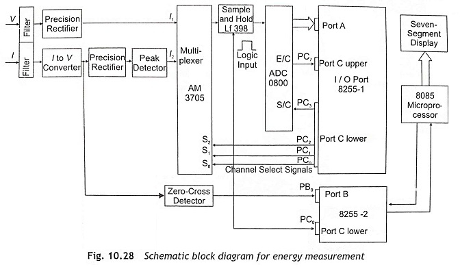
The block diagram of the microprocessor-based energy measurement is shown in Fig. 10.28. In any measurement system, it is necessary to interact the system with the microprocessor through a proper sensor generating voltage signal, depending upon the system performance and compatibility with the microprocessor.
The voltage across 0.01 resistances has been taken as the reference signal, which after isolation has been conveyed to the microprocessor through ADC and I/O ports. The voltage signal is also fed to the microprocessor through ADC and I/O ports.
Software development is the most interesting feature of the device since the monitoring system is solely dependent on software. The microprocessor initially assigns I/O ports as input ports and a clearing counter m for storing units of the energy consumed, receives electrical signals in succession from the respective sensors and keeps them in specified memory locations. Then allowing a very small pre-calculated time-delay, it continues to receive current signals, adds them to the previous ones, preserves the results in the same memory location and continues the cycle operations for sixteen complete cycles.