Digital Measurement of Time:
Principle of Operation of Digital Measurement of Time – The beginning of the time period is the start pulse originating from input 1, and the end of the time period is the stop pulse coming from input 2.
The oscillator runs continuously, but the oscillator pulses reach the output only during the period when the control F/F is in the 1 state. The number of output pulses counted is a measure of the time period.
Time Base Selector:
It is clear that in order to know the value of frequency of the input signal, the time interval between the start and stop of the gate must be accurately known. This is called time base.
The time base consist of a fixed frequency crystal oscillator, called a clock oscillator, which has to be very accurate. In order to ensure its accuracy, the crystal is enclosed in a constant temperature oven. The output of this constant frequency oscillator is fed to a Schmitt trigger, which converts the input sine wave to an output consisting of a train of pulses at a rate equal to the frequency of the clock oscillator. The train of pulses then passes through a series of frequency divider decade assemblies connected in cascade. Each decade divider consists of a decade counter and divides the frequency by ten. Outputs are taken from each decade frequency divider by means of a selector switch; any output may be selected.
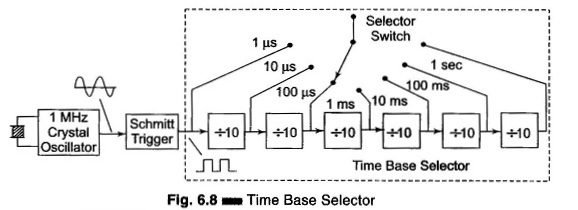
The circuit of Fig. 6.8 consists of a clock oscillator having a 1 MHz frequency. The output of the Schmitt trigger is 106 pulses per second and this point corresponds to a time of 1 microsecond. Hence by using a 6 decade frequency divider, a time base with a range of 1 μs – 10 μs – 100 μs – 1 ms -10 ms – 100 ms – 1 s can be selected using a selector switch.
Measurement of Time (Period Measurement):
In some cases it is necessary for Digital Measurement of Time rather than the frequency. This is especially true in the measurement of frequency in the low frequency range. To obtain good accuracy at low frequency, we should take measurements of the period, rather than make direct frequency measurements. The circuit used for measuring frequency can be used for the measurement of time period if the counted signal and gating signal are interchanged.
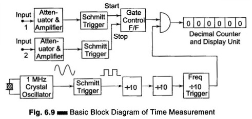
Figure 6.9 shows the circuit for Digital Measurement of Time period. The gating signal is derived from the unknown input signal, which now controls the enabling and disabling of the main gate. The number of pulses which occur during one period of the unknown signal are counted and displayed by the decade counting assemblies. The only disadvantage is that for measuring the frequency in the low frequency range, the operator has to calculate the frequency from the time by using the equation f = 1/T.
For example, when measuring the period of a 60 Hz frequency, the electronic counter might display 16.6673 ms, whence the frequency is
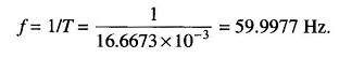
The accuracy of the period measurement and hence of frequency can be greatly increased by using the multiple period average mode of operation. In this mode, the main gate is enabled for more than one period of the unknown signal. This is obtained by passing the unknown signal through one or more decade divider assemblies (DDAs) so that the period is extended by a factor of 10,000 or more.
Hence the digital display shows more digital of information, thus increasing accuracy. However, the decimal point location and measurement units are usually changed each time an additional decade divider is added, so that the display is always in terms of the period of one cycle of the input signal, even though the measurements may have lasted for 10,100 or more cycles.
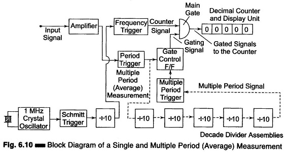
Figure 6.10 show the multiple average mode of operation. In this circuit, five more decade dividing assemblies are added so that the gate is now enabled for a much longer interval of time than it was with single DDA.
Ratio and Multiple Ratio Measurement:
The ratio measurement involves the measurement of the ratio of two frequencies. The measurement in effect is a period measurement. A low frequency is used as gating signal while the high frequency is the counted signal. Hence the low frequency takes the place of the time base. The block diagram for the ratio measurements are multiple ratio is shown in Fig. 6.11.
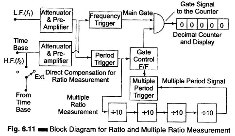
The number of cycles of high frequency signal f1 which occur during the period of lower frequency signal f2 are counted and displayed by the decimal counter and display unit. In multiple ratio measurements the period of low frequency signal is extended by a factor of 10,100, etc. by using DDAs.