Three Wattmeter and Two Wattmeter Method:
In this method, the three wattmeter are connected in the three lines as shown in Fig. 9.45, i.e. the current coils of the three wattmeter are introduced in the three lines, and one terminal of each potential coil is connected to one terminal of the corresponding current coil, the other three being connected to some common point which forms an effective neutral n.
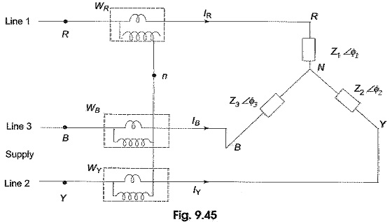
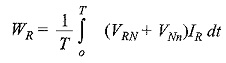
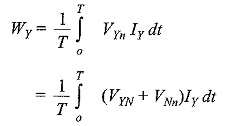
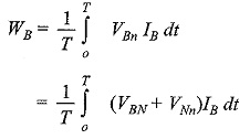
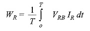
The load may be either star-connected or delta-connected. Let us assume a star-connected load, and let the neutral of this load be denoted by N. Now the reading on the wattmeter WR will correspond to the average value of the product of the instantaneous value of the current IR flowing in fine 1, with the voltage drop VRn, where VRn is the voltage between points R and n. This can be written as VRn = VRn + VNn, where VRn is the load phase voltage and VNn is the voltage between load neutral, N, and the common point, n. Similarly, VYn = VYN + VNn, and VBn = VBn + VNn. Therefore, the average power, WR indicated by the wattmeter is given by
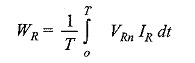
where T is the time period of the voltage wave
Similarly,
and
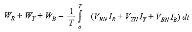
Total average power = WR + WY + WB
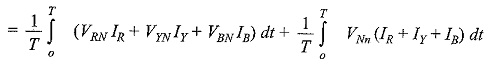
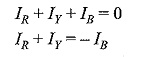
Since the system in the problem is a three-wire system, the sum of the three currents IR , IY and IB at any given instant is zero. Hence, the power read by the three wattmeter is given by
If the system has a fourth wire, i.e. if the neutral wire is available, then the common point, n is to be connected to the system neutral, N. In that case, VNn would be zero, and the above equation for power would still be valid. In other words, whatever be the value of VNn, the algebraic sum of the three currents IR , IY and IB is zero. Hence, the term VNn (IR + IY + IB) would be zero. Keeping this advantage in mind, suppose the common point, n, in Fig. 9.45 is connected to line B. In such case, VNn = VNB; then the voltage across the potential coil of wattmeter WB will be zero and this wattmeter will read zero. Hence, this can be removed from the circuit. The total power is read by the remaining two wattmeters, WR and WY.
Total power = WR + WY
Let us verify this fact from Fig. 9.46.
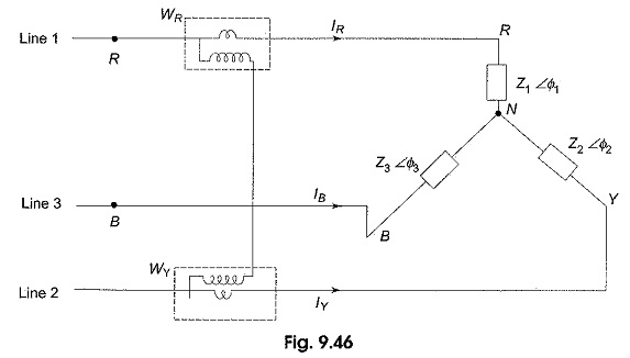
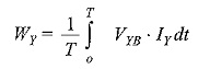
The average power indicated by wattmeter WR is
and that by
Also
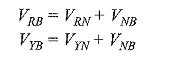
We know that
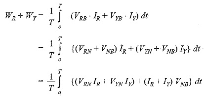
Substituting this value in the above equation, we get
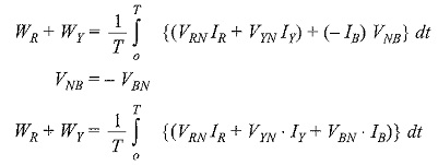
which indicates the total power in the load.
From the above discussion it is clear that the power in a three-phase load, whether balanced or unbalanced, star-connected or delta-connected, three-wire or four wire, can be measured with only two wattmeters as shown in Fig. 9.46. In fact, the two wattmeter method of measuring power in three-phase loads has become a universal method. If neutral wire is available in this method it should not carry any current, or the neutral of the load should be isolated from the neutral of the source.
The current flowing through the current coil of each wattmeter is the line current, and the voltage across the pressure coil is the line voltage. In case the phase angle between line voltage and current is greater than 90°, the corresponding wattmeter would indicate downscale reading. To obtain upscale reading, the connections of either the current coil, or the pressure coil has to be interchanged. Reading obtained after reversal of coil connection should be taken as negative. Then, the algebraic sum of the two wattmeter readings gives the total power.