Overcurrent Protection Relay in Power System:
The technique of Overcurrent Protection Relay in Power System is still widely used as a means of detecting faults on distribution system and on transmission lines fed from one end. In the case of lines fed from both the ends it is used along, with directional relays. Overcurrent Protection Relay are also used in conjunction with distance relays to provide backup protection.
Fault current level detectors are termed overcurrent relays; in their static form they are more complicated as compared to their electromagnetic counterpart.
The static form offers the following advantages over the electromagnetic form:
- Low burden on CT, so that smaller CTs are required.
- Compactness of the unit and reduction in panel space.
- Instantaneous reset possible because of the absence of moving parts, which facilitates the application of automatic re-closing of breakers.
- Less maintenance, long life and not affected by shock and
- No overreaching tendencies and great accuracy of the characteristics.
In conventional overcurrent relays, it is assumed for all practical purposes that the time of tripping varies inversely as the operating current of the relay.
Operating Principles of Static Time Current Relays:
The static Overcurrent Protection Relay in Power System consists of a rectifier unit which converts the a.c. signals to d.c. levels, followed by overload level detector timing circuit, level detector and a trip. Figure (12.6) represents the block schematic of a time-current relay.
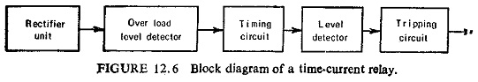
The current from the line CT is reduced to 1/1000th by an auxiliary CT, the auxiliary CT has taps on the primary for selecting the desired pickup and current range and its rectified output is supplied to an overload level detector and an RC timing circuit. When the voltage on the timing capacitor has reached the value for triggering the level detector, tripping occurs.
Several methods for timing and curve shaping are available. The timing capacitor is generally charged by a voltage derived from the CT current, e.g. from the voltage across a nonlinear resistor through which the rectified current flows. This also facilitates the shaping of the time-current characteristic to a desired curve by nonlinear resistors and RC networks.
Time Current Characteristics:
A general expression for the operating time of a time-current relay is:
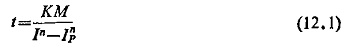
where
t = time of operation in second
K = design constant
M = time multiplier setting (TMS)
I = multiple of tap current
IP = multiple of tap current at which pickup occurs
n = index number which is empirical.
The nature of the curves and their degree of inverse characteristics have been standardized. According to British Standards following are the specified curves:
Standard inverse (IDMT),
![]()
Standard very inverse,
![]()
Standard extremely inverse,
![]()
It can be seen that near about both the axes the curve become asymptotic in nature. This gives rise to two terms; the pickup current below which the relay practically does not operate and a definite minimum time of operation, which cannot be reduced further however high the relay current may be. These are clear from Fig. (12.7).
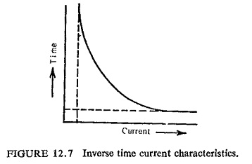
It is possible that future characteristics will be of the form t = k/In which will give a straight line on a log t/log I graph. This curve therefore will no longer be asymptotic to the pickup value of current, the pickup will be controlled by a separate device, similarly the definite time portion of the characteristic can be-provided by a separate unit.
Directional Overcurrent Relays:
For obvious reasons of obtaining selectivity overcurrent relaying is made directional. The device reacts to the sign of the power which depends on the position of fault in relation to the point where the protective gear is installed. As the static comparators are very sensitive and it is comparatively easier to make a static directional unit reliable down to a voltage well below the minimum fault voltage there is not much of a problem of discrimination at a low voltage.
Directional Units: Hall effect generator described earlier which gives a linear cosine product output, and the rectifier bridge phase comparator described already which has a cosine output limited by the rectifier characteristics are normally used as directional units. The Hall crystal as phase comparator has gained popularity only in U.S.S.R.
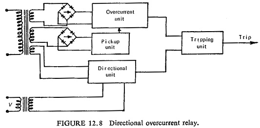
The operation of a rectifier bridge phase comparator has already been explained. Figure (12.8) shows the block schemetic of a directional Overcurrent Protection Relay in Power System.