Overcurrent Protection of Feeders:
Overcurrent relays offer the cheapest and the simplest protection for lines. The maximum load currents must be known to determine whether the ratio of the minimum fault current to maximum load current is high enough to enable simple overcurrent operated relays to be used successfully. This criterion is chosen in order to prevent the possibility of misoperation under normal operating conditions. This form of protection can be applied only to simple systems. The relays need readjustment or even replacement whenever a change in the system is made. The operating times are generally large. Overcurrent Protection of Feeders may be divided into two categories:
-
Nondirectional time and current grading; and
-
Directional time and current grading.
Nondirectional Time and Current Grading:
It is possible to have time-graded systems, current-graded systems or a combination of the two, i.e. current/time-graded systems.
Time-Graded Systems: To ensure selectivity of operation under all circumstances in a radial feeder, the operating time of the protection is increased from the far end of protected circuit towards the generating source. This is very conveniently achieved with the help of definite-timedelay relays, which usually consists of an instantaneous overcurrent relay followed by a timing relay the contacts of which trip the breaker. It has a more accurate time setting which is independent of CT saturation thus allowing closer grading times between successive circuit breakers. As the number of relays in series increase, the operating time increases towards the source. Thus the heavier faults near the generating source are cleared after a longer interval of time, which is a drawback. Its main application is in systems where the fault levels at the various locations do not vary greatly and hence the advantage of the inverse type of relay cannot be used.
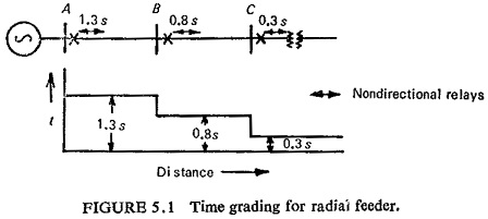
Figure (5.1) illustrates the principle of time graded Overcurrent Protection of Feeders of a radial feeder. The protection is provided at the sending end of each section A, B and C. For a fault beyond C the breaker at C operates first and the protection at B and A act as backup protection. For faults between B and C the relay at B trips breaker at B and so on. The time setting of the successive relays differ by an interval known as time delay step, which is a factor of (i) fault clearance time of circuit breaker, (ii) finite contact gap to ensure nonoperation, (iii) overtravel of relays, and (iv) relay and CT tolerances.
Normally the time delay step lies between 0.3s and 0.5s. A time delay step of 0.5s is a safe value which is taken in this illustration.
Current-Graded Systems: It is based on the fact that the short-circuit current along the length of the protected circuit decreases as the distance from the source to the fault location increases. If the relays are set to pickup at a progressively higher current towards the source then the disadvantage of the long time delays that occur with time grading can be partially overcome. This is known as current grading. Each relay would be set to pickup at a progressively higher current towards the source. Such relays are known as high-set-overcurrent relays.
A simple current-graded scheme applied to the system of the form shown in Fig. (5.1) would consist of high-set-overcurrent relays at A, B and C with settings such that the relay at A would operate for faults between A and B, the relay at B. for faults between B and C, the relay at C for faults beyond C. In practice the following difficulties are experienced:
- The relay cannot differentiate between faults which are very close to, but are on each side of B, since the difference in the current would be extremely small.
- The magnitude of the fault current cannot be accurately determined, since all the circuit parameters may not be known.
- The accuracy of relays under transient conditions is likely to be different.
Hence for discrimination the relays are set to protect only part of the feeder, usually, 80%. For this reason current grading alone cannot be used, but it may, with advantage, be added to a time-graded or IDMT relay system.
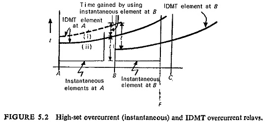
Figure (5.2) shows the characteristics of the combined high-set overcurrent (instantaneous) and IDMT Overcurrent Protection of Feeders. For correct discrimination the instantaneous elements must be set so that they do not operate for faults beyond the Overcurrent Protection of Feeders. As a general rule a margin of 50% is recommended, e.g. the primary operating current of the instantaneous relay at A is not less than 150 % of the maximum fault current at B. The margin allows for errors and for the overreach of the instantaneous relay on offset transients.
Transient overreach occurs when the current wave contains a d.c. component and is therefore offset from the zero axis; it is defined as follows:![]()
where
A = relay pickup current in steady state rms amperes.
B = the steady state rms current which when fully offset will just pick up the relay.
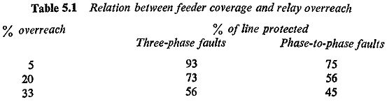
The degree of feeder coverage obtained with relays having 5%, 20% and 33% overreach is shown in Table 5.1 for a system where the ratio of fault current at the near and far end is 5: 1.
It can be seen in Fig. (5.2) that there is a permissible reduction in time interval between the IDMT relays. The IDMT relay at A must discriminate with the instantaneous element at B for a fault at B, and with the IDMT relay at B for a fault at F (the limit of reach of the instantaneous element at B). If there were not an instantaneous relay at B the IDMT relay at A would require the slower characteristic curve (i).
Schemes where speed of fault clearance is proportional to the current are usually preferred, i.e. the higher the current the faster the relay operates. The schemes that follow have this characteristic.
Current/Time-Graded Systems: Current/time grading is possible with inverse-time Overcurrent Protection of Feeders. The most widely used is the IDMT characteristic where grading is possible over a wide range of currents and the relay can be set, within the design limits, to any value of definite minimum time required. Other inverse characteristics, viz. very inverse and extremely inverse characteristics are also sometimes employed for the same purpose. If the fault current reduces substantially as the fault position moves away from the source some advantage can be gained by using very inverse relays instead of IDMT relays. The long operating time at low values of overloads of IDMT relays make extremely inverse relays eminently suitable. Where grading with fuses is required it is the ideal choice.
The factors to be considered and the methods of grading IDMT relays are discussed below.
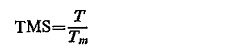
There are two basic adjustable settings on all inverse time relays; one is the time multiplier setting (TMS), and the other is the current setting usually known as the plug setting multiplier (PSM).
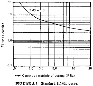
The time setting is adjustable from 0 to 1.0, the value selected being a multiple of the operating time shown on the time/current characteristic curve, which is drawn for a time setting of 1.0 (TMS) shown in Fig. (5.3).
The time multiplier setting for an inverse time relay is defined as;
where
T = the required time of operation
Tm = the time obtained from the relay characteristic curve at TMS=1.0, and using the PSM equivalent to maximum fault current.
Thus, if the TMS is 0.1 and the time obtained from the curve, for a particular current is 4.0 seconds the actual operating time will be 4.0 X 0.1=0.4 second. In other words, if the time from the curve is 4.0 seconds and the operating time required is 0.4 second the TMS should be 0.4/4.0=0.1. Increasing the TMS has the effect of moving the curve higher on the time scale.
Current setting is adjusted by means of a tapped plug bridge hence known as PSM.
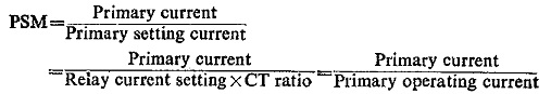
where, as is usually the case, the rated current of the relay is equal to the rated secondary current of the CT. For example, if the maximum fault current that can flow through the relay location is 3000 A and the relay is set to operate at 200 primary amperes, then PSM=3000/200=15, or if the primary current is 3000 A and the relay current setting is 50% and the CT ratio is 400/5, then
![]()
For the same primary current and a relay current setting of 200%
![]()
Coordination of Inverse-Time Overcurrent Relays: Procedure for the selection of pickup or current setting and the time setting is indicated below.
Selection of current setting: It is necessary to calculate the maximum fault current which can occur at each relay position. A three phase fault under maximum generation gives the maximum fault current and phase to phase.fault under minimum generation gives the minimum fault current. These are the two extreme values of fault current and the relay has to respond between these conditions. On a radial system the lowest setting must be at the farthest end; the settings being increased for the subsequent relays towards the source. As per Indian Standards the operating value should not exceed 130% of the setting, hence
![]()
Selection of time setting: For selective operation when there are a number of relays connected in series, the relay farthest from the source should be sot to operate in the minimum possible time. For succeeding relays towards the source a time delay step is given. For inverse-time Overcurrent Protection of Feeders the time setting should be done at the maximum fault current. if the relay has proper selectivity at maximum fault current, it will automatically have a higher selectivity at the minimum fault current, as the curve is more inverse on lower current region.
Directional Time and Current Grading:
In the plain radial feeders the discrimination is obtained by means of the. relay time and current setting adjustments only. To obtain discrimination where feeders other than radial feeders are employed, it is usually necessary to incorporate a directional feature in the protection, as will be clear from the following cases. Three separate cases will be considered: (a) parallel feeders, (b) tee’d parallel feeders, and (c) ring mains.
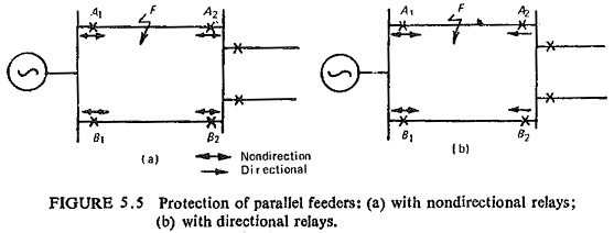
Figure (5.5) shows the case of parallel feeder; with nondirectional relays it can be seen that with a fault anywhere on the feeder point F the supply will be disrupted completely for both the feeders irrespective of the relay settings chosen. To ensure discrimination it is usual to have relays A2 and B2 as direction sensitive such that they operate for faults occurring in the feeder in the direction indicated by the arrows (away from the bus) shown in Fig. (5.5b). Furthermore directional relays A2 and B2 should operate before nondirectional relays A1 and B1. For this reason they are given lower time and current settings than A1 and B1. Usually a directional relay is required at one end of each feeder with a nondirectional relay at the other end. Directional overcurrent relays are graded in the same way as the nondirectional overcurrent relays already explained. Directional overcurrent relays require a voltage source in addition to the current source.
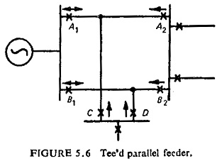
Figure (5.6) shows the case of a tee’d parallel feeder, where again for discriminative reasons the relays on the source end bus must be nondirectional while the relays on the load end buses must be directional relays with their direction for operation corresponding to fault current flowing into the feeder. Furthermore, directional relays are set for lower time and current settings than the nondirectional ones, so that the former operate before the latter.
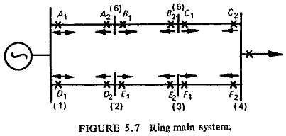
Figure (5.7) shows the case of a ring main system. In order to achieve discrimination for faults the relays associated directly with a faulty section of the ring should operate. It will again be noted that the relays at the source bus A1 and D1 need not be directional relays. In fact it is advisable that A1 and D1 should not be directional. Otherwise for faults close to the source bus there may be nonoperation. The direction of operation for other directional relays is also shown in Fig. (5.7).
Relay settings are determined by considering the grading first in one direction and then in the other, working backwards to the power source. For instance, considering the counterclockwise circuit D1—A2 in Fig. (5.7) the relay settings at A2 are calculated first; the relay must receive atleast twice its setting current for a fault at A1 end of the A2A1 feeder with the A1 circuit breaker open and the fault current fed around the ring from D1 with the minimum generating conditions at the source. The minimum setting of the TMS can be used at A2, but the current setting must, be sufficient for the relay to withstand thermally the full load of all the substations, i.e. (1) to (6).
The relay settings at B2 are calculated next in a similar manner. With a fault at A2, the circuit breaker at A1 open and maximum generation connected. The relay at A must discriminate with the relay at A2. The process is repeated for relays C2, F1, E1 and D1.
The setting calculations for the relays in the clockwise circuit A1—D2 are now undertaken, working backwards from D2 to A1. Care must be taken that the midpoint of the ring is fully protected.