Differential Protection Relay in Power System:
A Differential Protection Relay in Power System scheme compares quantities derived from the input and output currents of the protected circuit in such a manner that, for all healthy system and through fault conditions, the quantities balance and the protection is inoperative, while for internal fault conditions the balance is disturbed and the protection operates.
For small lengths of the order of 25 km, pilot wires are used for transmission of information from one end to the other so that the relays can effect a continuous comparison of quantities derived at the two ends. However, for long lengths the method becomes impracticable and costly and so carrier schemes are usually applied. Such schemes have a great deal in common with pilot wire schemes. The pilot wire differential and the carrier Differential Protection Relay in Power System are unit type of protection, where absolute selectivity is obtained.
Since all differential feeder protection systems utilize a summation device to produce a single-phase output from the three-phase system at the two ends, the protection characteristic is best expressed in terms of the complex ratio of these summated outputs. In practice, a summation transformer or a sequence network is used to derive a single phase relaying quantity from the three-phase currents at each end of the primary circuit.
Effectiveness of Comparison:
The use of summation device which is an integral component of every differential feeder protection, results in an overall reduction in the discriminating margins, owing to the condensation and consequent reduction of information contained in the compared quantities.
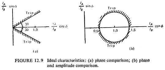
Idealized characteristics of differential feeder protection scheme, under conditions of normal load or through fault, neglecting primary circuit capacitance current and leakage current together with errors in transformation are shown in Fig. (12.9). The relaying quantities at both ends of the transmission circuit will be identical in magnitude and phase, so that their phasor ratio α = IA/IB = 1 + j0 = 1∠0°. Two types of characteristics are plotted showing the threshold boundaries in terms of the effective ratio of outputs from the summation devices at the two ends A and B of the protected line. Figure (12.9a) shows phase comparison while Fig. (12.9b) shows both phase and amplitude comparison. Pilot wire systems may employ either of the above characteristics while carrier current systems employ pure phase comparison.
In practice the pilot wire protection system characteristics tend to be variable and unpredictable because a relay having a closed threshold characteristic under lightly loaded conditions may present a pure phase comparison characteristic under saturated fault conditions. This is because of the fact that the pilot circuit parameters are often inadequately considered, with the result that the discriminating margins are seriously affected.
Basic Pilot-Wire Protection Scheme:
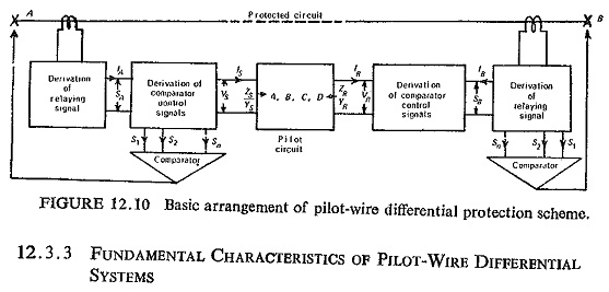
A system of pilot-wire Differential Protection Relay in Power System is shown schematically in Fig. (12.10), for simplicity only one phase is shown. A single-phase relaying signal is derived from the three phases of the protected circuit at each end of protected zone, and they are compared in the pilot link. When conditions at each end of the circuit are the same, corresponding to healthy or through-fault conditions, the relaying signals should be of near equal amplitude and phase and a balance should be achieved between them, thereby giving rise to only a small residual signal in the protection system.
Under internal fault conditions, on the other hand, the balance should be disturbed to an extent that permits the derivation of reliable control signals to trip the circuit breakers associated with the protected circuit. High degree of stability in the balance condition for the wide range of external loading and fault conditions is required without impairing its ability to detect all internal fault conditions.
Fundamental Characteristics of Pilot-Wire Differential Protection Relay:
In Fig. (12.10) keeping the current IA fixed and assuming that an output voltage VS is produced directly proportional to this current, the corresponding voltage VR at the remote end can be considered to vary in phase and magnitude. As it does so the input current IS to the pilot circuit will vary, and it is required to investigate the locus of this current to determine the discriminating margin available between internal and external fault conditions. A relay characteristic must then be chosen such that the change in pilot-circuit current produced by the primary-circuit currents under internal and external fault conditions can be used to provide definite discrimination.
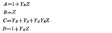
The characteristics of the pilot circuit can be represented by the 4-terminal network having constants A, B, C, D these being related by the well known equations
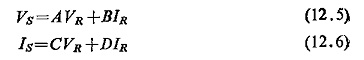
For an equivalent π-network the values of A, B, C, D are:
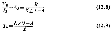
Taking the case where VR is fixed and VS varying in phase and magnitude, then VS = KVR ∠ θ, where K is the modulus of the ratio VS/VR and θ is the phase angle between the two voltages. Then substituting in Eq. (12.5) for VS we have![]()
from which, we get
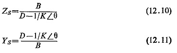
Similarly for the remote end
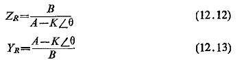
Since the current at end R is reversed, then the impedance and admittance looking into the pilot circuit is given by
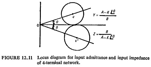
These expressions give a locus diagram in terms of input impedance or admittance for a generalized 4-terminal network. For the impedance equation the locus of input impedance is a circle of radius BK/(A2-K2) at a distance of AB/(A2-K2) from the origin (Fig. (12.11)). The admittance equation also represents a circle and is more convenient where the radius is K/B and the distance of centre from the origin is A/B. It can be noted that by varying K, different concentric circles can be drawn. Obviously to draw these circles constants A and B are required, which can be calculated by the open and short-circuit impedance of the pilot-wire circuit.
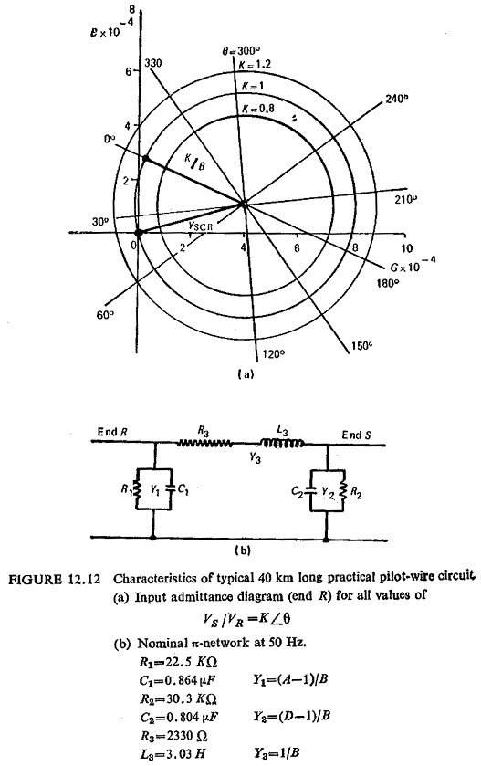
From these measurements A/B = YSCR (short-circuit admittance viewed from end R) and
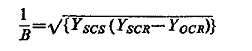
where YSCS is the short-circuit admittance of the pilot circuit viewed from end S and YOCR is the open-circuit admittance viewed from end R. On this diagram can also be plotted the relay characteristics expressed in terms of impedance or admittance measurement. The relay characteristic can then be adjusted to embrace the actual phase and magnitude variations of the input from the power system under healthy conditions.
The input-admittance locus diagram of Fig. (12.12a) is plotted for a typical practical pilot-wire circuit, when θ is zero and K is unity, the conditions at the two ends of the protected circuit are the same, and the protection should therefore restrain. If K remains unity but θ increases to 180°, this represents an internal fault fed equally from the two ends, and presents the ideal antiphase condition of the relaying signals for a fault legitimately within the protected zone. For the range of fault conditions encountered in normal practice, as manifested at this stage in the K and θ quantities, there will be a correspondingly wide range of apparent pilot-circuit admittance, for which the protection should positively operate. In meeting these requirements, one possibility, for example, is for the restraining zone to be circular, the centre of the circular characteristic coinciding with the ideal through fault condition for which K=1, θ=0, as shown in Fig. (12.13).
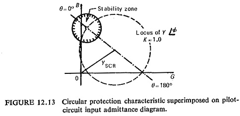
Tripping is then effected everywhere in the admittance plane without and only without the defined restraining zone.
Admittance Characteristics of Two Input Comparators:
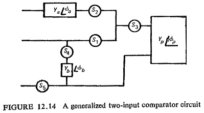
A generalized two-input comparator circuit is shown in Fig. (12.14), where
alternative signal inputs can be derived and compared in various combinations. The different available signal inputs are:
Irrespective of the number of signals, the comparison may be of the amplitudes of the control quantities, independent of their phase relationships, or alternatively, of their phase relationships, independent of their amplitudes.
Coordination with Remote-End Characteristic:
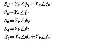
Transformation from Admittance Plane to the Platte of the Complex Ratio of Relaying Signals. It is possible to interpret the admittance diagram of Fig. (12.12) in the plane of the ratio of relaying signals. Using the input admittance of Fig. (12.12), the origin of the latter plane shown at zero, ‘0’, in Fig. (12.15a) is given by the condition of the S voltage being zero, and so coincides with the input admittance at end R with end S short circuited. The real axis of the signal ratio plane must pass through the points at which the relaying signals are in phase and in antiphase, and the new plane is then as shown in Fig. (12.15). Furthermore, where the system is operating in a linear mode, the ratio VS/VR is identical to the ratio SA/SB and so the protection characteristics may be shown directly in the plane of the complex ratio of the relaying signals SA and SB, as derived from the phase-current summator. Although in Fig. (12.15a) negative values of the real part of the ratio VS/VR are drawn to the right of the origin, this is reversed in Fig. (12.15b) so that positive values appear to the right in the ordinary way.
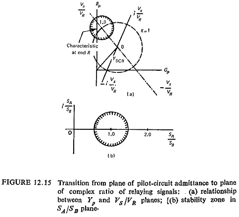
Inverse Characteristics: The characteristics so far derived from applications of the appropriate restraining criteria are those that obtain at each end of the protected circuit, without giving consideration to the effect that the characteristic at one end has on that at the other. Now the characteristic at end A may be shown directly in the SB/SA plane, and similarly that at end B in the SA/SB plane, which is the local one at that end. The characteristic at one end, therefore, appears as its inverse at the other, and it is the combination of the local and the inferred remote-end characteristics which defines the resultant zone of stability for the protective scheme as a whole. Figure (12.16) represents the local end circular characteristic and the equivalent far end characteristic. For conditions completely outside the local and inverse characteristics, both ends of the protection trip together. In the range that is covered by only one characteristic, the two ends trip sequentially. The common local area represents the range of conditions for which both ends restrain.
Where the pilot-wire schemes are applied over long pilot circuits, particularly where these employ low insulation telephone-type cores, some part of the protection characteristic is influenced by the action of the voltage limiter
Performance of Pilot-Wire Protection Systems:
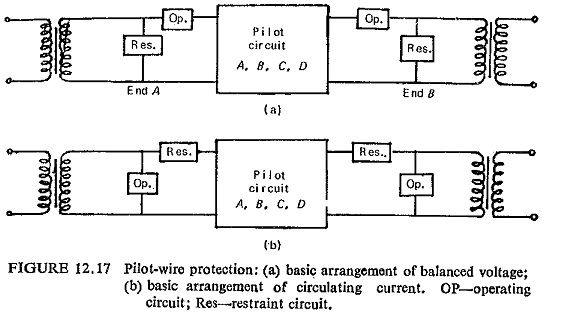
The basic pilot-wire protection systems may employ either the balanced voltage or the circulating current principles. Balanced voltage schemes are voltage driven whereas circulating current schemes are current driven. The former method finds wider application to feeder protection because it does not impose limitations on pilot length and linearity of summation devices like the latter. Figure (12.17) shows the basic circuit of an uncompensated balanced-voltage and circulating-current schemes. It may be noted that the position of the operating and restraint circuits have been interchanged.
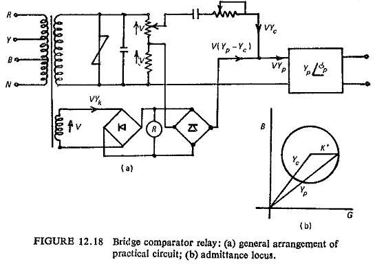
Bridge-Comparator Method Used in Balanced-Voltage Schemes: For a practical balanced-voltage protection scheme with shunt compensation and utilizing amplitude comparison between the operating and restraint quantities, it is desirable that the circuit should be tuned so that the overall compensated pilot circuit Y(P+C) presents zero admittance to the relays for the condition VS/VR = 1∠0.