Voltage Balance Differential Relay:
In this voltage balance differential relay arrangement, two similar current transformers are connected at either end of the system element under protection (such as a feeder) by means of pilot wires. The relays are connected in series with the pilot wires, one at each end. The relative polarity of the CTs is such that there is no current through the relay under normal operating conditions and through fault conditions [Fig. 9.57 (a)]. The CTs used in such protection should be such that they should induce voltages in the secondary linearly with respect to the current. Since the magnitude of fault current is very large, in order that the voltage should be a linear function of such large currents the CTs should be air-cored.
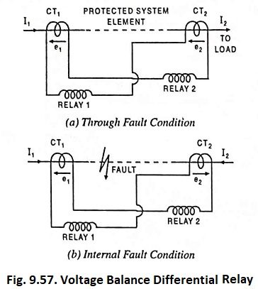
When a fault occurs in the protected zone, the currents in the two primaries will differ from one another and so voltages induced in the secondaries of the CTs will differ and circulating current will flow through the operating coils of the relays. Thus the trip circuit will be closed and the circuit breaker will open.
To provide for capacity currents, the relays employed may be overcurrent type which should operate only when the difference of the currents on both sides exceeds certain value.
In this voltage balance differential relay system no restraining coil or balancing resistance or overload coil is required.
Advantages, Disadvantages and Uses
Though this method is more reliable that current balance or circulating current system but has great disadvantage that CTs do not carry current so acts as open circuited and inserts a high impedance in the circuit. This method may be employed for protection of feeders, alternators and transformers. For use on transformers, the turn-ratio of power transformers must be kept in view.