Differential Relay Application:
The principle of operation depends on a simple circulating current principle where the difference of the currents of the two CTs flows through the relay under normal conditions or even under faults outside the protected section. This is illustrated in Fig. (4.22). The relay R is a simple comparator which compares current magnitude, power direction or relative phase of the currents at the ends of the protected zone. In the electromagnetic form it consists of two electromagnets exerting torques in opposition on an armature carrying contacts. These electromagnets are excited by the currents from the two CTs. Faults inside the protected zone however cause the two currents to flow in the same direction through the relay R, thus producing a resultant positive torque which closes the contacts of the trip circuit of the circuit breakers A and B on the two ends. This is commonly known as Merz Price principle. Pilot wires are generally necessary between relaying points, and the provision of these is a major consideration in the Differential Relay Application of this form of protection.
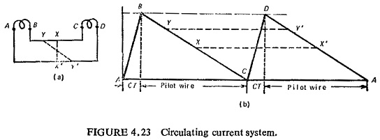
In the basic circuit of Fig. (4.23a) the CTs are connected in series by means of pilot wires. The whole of the secondary emf of both CTs is used to overcome the combined impedance of the CTs and pilot wires. The voltage distribution is illustrated in Fig. (4.23b), where AB and CD are secondary emfs of the CTs which are equal and BC and DA represent the voltage drops in the two pilot wires. It can be seen that there are an infinite number of corresponding points at the same potential on the two pilot wires such as XX’ and YY’, It is also clear that the pilots constitute the only burden on the CTs, this burden being shared equally so long as there is no connection between the pilot wires other than at equipotential points such as XX’ and YY’ etc.
In practice the relay is connected across the pilot wires and if the connections are not at equipotential points the burdens on the two CTs are unequal, although the current in the two CTs is same. This may cause the heavily loaded CT to saturate during through-fault conditions. This results in dissimilarity of voltage and phase angle characteristics of the CTs producing an out-of-balance current which causes spurious operation of the relay. The problem can be tackled in two ways. The first is by biasing the relay and the second is by using a high impedance relay with a low current setting. This is illustrated below.
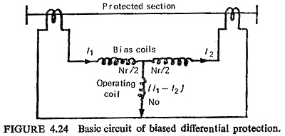
The effect of the bias is to enable the impedance of the relay operating circuit to be reduced for a given value of through-fault stability. The bias is obtained by circulating the through-fault secondary current through an additional winding which exerts a restraining force or bias on the movement. The basic circuit connections are shown in Fig (4.24). Normally no current flows in the operating coil under through-fault conditions, but owing to imperfect matching of the CTs some spill current may be present. This spill current will flow in the relay operating circuit but will not cause operation unless the operating bias current ratio for which the relay is set is exceeded. The magnitude of the current to cause operation is not constant but automatically increases as the circulating current increases and a definite ratio exists between the two quantities.
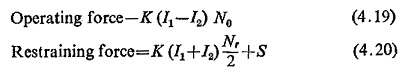
This ratio can be determined by considering the forces acting on the relay movement:
where
No = number of turns of operating coil
Nr = number of turns of restraining coil
K= constant
S = mechanical restraint
The electrical operating and restraining forces are equal at the balance point of the relay; neglecting the mechanical restraint we have
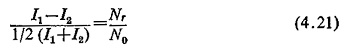
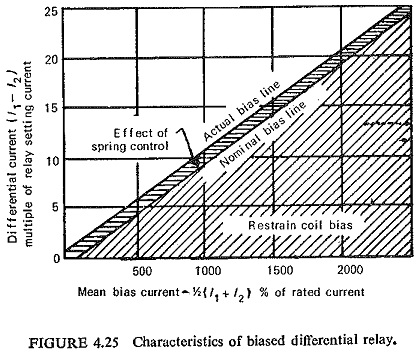
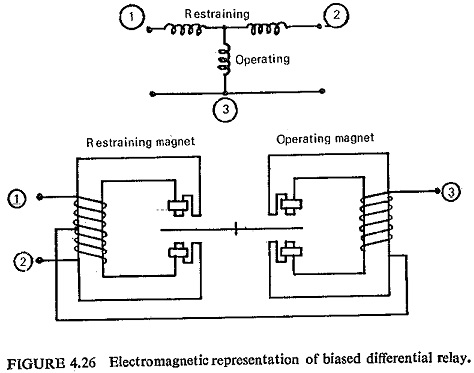
This equation shows that the characteristic has a slope determined by the ratio Nr/N0 or with given relay constants the per unit bias is defined as the difference current divided by the mean circulating current and is a constant ratio for all current magnitudes (Fig. (4.25)). This ratio is more commonly expressed as percentage bias, where percentage setting or bias is in terms of the nominal current rating of the CTs. With an internal, fault a current proportional to the fault current flows in the relay operating winding, and the protection setting is usually stated for the condition of an infeed from one end only. Any simultaneous through load current flows in the relay bias winding and thus increases the setting. In the simplest electromagnetic form the relay is shown in Fig. (4.26).
The high impedance relay requires 50 to 100 V and only a small current to cause operation (in effect a voltage operated relay). The maximum voltage developed during through-fault conditions can be computed and the relay voltage setting arranged to be above this value. In the Differential Relay Application of high speed differential protection the transient d.c. component of fault current must be considered. Its effect is to cause a unidirectional buildup of flux in the CT core producing saturation and consequent large ratio errors. Where more than one circuit is involved (e.g. with bus bar protection) the asymmetry may cause a different degree of saturation in each of the balancing CTs.
Referring to Fig. (4.27) R1 and R2 are the resistances on each side of the relay, i.e. lead resistance plus CT secondary resistance (for wound-type CTs
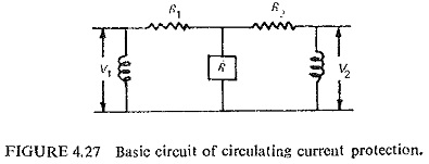
the leakage reactance must be included). Let us consider the most adverse condition for through-fault balance, viz. one CT completely saturated by the d.c. component of the fault current balancing against an ideal- current transformers. The saturated CT then contributes nothing to maintain the relay connection points at zero voltage and behaves as a low impedance connected in parallel with the relay operating coil. So either the saturation should be avoided by air cored CTs which will mean large size or the relay should be accordingly designed.
Assuming the right-hand CT to be fully saturated, i.e. V2 = 0 and the left-hand CT to be ideal with a relay of Z0 operating circuit impedance, we get
![]()
Substituting Nr/N0 = B in Eq. (4.21)
![]()
Simplifying Eqs. (4.22) and (4.23)
![]()
or the relay operating circuit impedance
![]()
Thus for a given CT secondary resistance, stability can be ensured by adjustment of either the relay bias slope or by increasing the impedance of the relay operating coil circuit.
The relay setting voltage is given by
![]()
where Is is the relay setting current.
By using a relay which is insensitive to the d.c. component and which operates on rms values, the maximum operating voltage across the unbiased relay under the conditions of maximum through-fault is I1R2. The relay setting voltage for stability must be at least equal to this value. Thus the ratio of setting voltages for the biased and unbiased relays is
![]()
For a typical case of through-fault stability up to 15 times CT rated current and a biased relay having a setting of 5% and a slope of 5 %. This ratio becomes 0.05 (20-0.5)/15 or approximately 1:15, i.e. for a given through-fault stability limit the setting voltage of the unbiased relay is 15 times that of the 5% slope relay. This ratio increases as the bias slope increases and for a 20% slope relay having the same 5% setting it becomes 1 : 66. The effect of the bias feature is thus to enable the relay setting voltage to be reduced for a given value of through-fault stability.
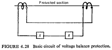
An alternative solution to the problem of a suitable relaying connection is the use of a voltage-balance arrangement. The principle of voltage balance protection is shown in Fig. (4.28). Relays are connected in series with the pilots, and the relative polarity of the CTs is such that there is no pilot current for the conditions of load or through-fault. Differential Relay Application is no longer used in its elementary form, but it has led to the development of a wide range of schemes using biased relays.
Pilot channels are very expensive and hence it is customary to combine the currents at each terminal into a single current which is possible by using summation transformers or by phase sequence networks. Only two wires are required with high impedance relays, the relays at each end responding to the common voltage between wires. A resistance of the order 1 KΩ can be tolerated, so that telephone wires can be used.
Differential Relay Application are ideally suited for the protection of compact items of electrical plant such as generators, busbars, transformers, reactors, capacitors, motors, short transmission lines, etc.