Simple Testing Station:
In these Testing Station the short-circuit power is supplied by specially designed short-circuit generators, driven by induction motors. A simplified diagram of such a testing station is shown in Fig. (18.1).
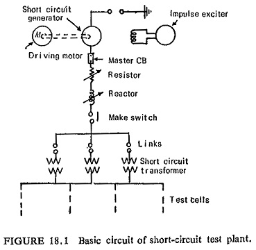
The magnitude of the test voltage and the short-circuit current can be selected within wide limits by adjusting generator excitation and connection of the transformers. Further limitation and variation of current independent of voltage can be effected by means of tapped resistors and reactors. This also serves to control the power factor.
The circuit is closed by a specially designed make switch, designed for closing on very heavy currents, but never called on to break currents. Synchronized closing is controlled by means of a small pilot generator coupled to the generator shaft and can be very accurately set to occur at any instant within the voltage wave.
In this way the phase position at the commencement of short circuit can be selected and a short-circuit current either fully symmetrical or with any degree of symmetry can be produced. In order to avoid unnecessary destruction in the event of failure of circuit breaker under test, the master circuit breaker is provided as a backup protection and opens.
The testing station are of very compact design with short connection for short circuit so that the generator output may be utilized to full extent. They have very high natural frequency and by adding capacitors any desired frequency can be obtained. The breaker to be tested is enclosed in a test cell made of reinforced concrete having a provision of observation while test is in progress.
The recording equipment is located in a control room which is suitably remote from the test cell but situated so as to allow the test breaker to be observed. The control operations are carried out from the control room.