Fiber Optic Testing:
The Fiber Optic Testing focuses primarily on the processes and equipment used during and after the installation of fiber optic cables and their associated equipment. The Fiber Optic Testing is performed by the engineer or technician to guarantee acceptable performance standards.
Splices must be tested for optical clarity. They must not exceed certain loss values, Fiber Optic Testing must be made on each splice as it is completed; a failure requires resplicing. One way to test a splice is to use an Optical Power Meter.
The optical power meter is similar to the voltohmmeter in application but measures the optical resistance (losses measured in dBm or dBM) of a cable before and after installation and provides a comparative analysis of the splices.
The range of the meter is adjustable. Sensors from 400 to 1800 nm and attenuation levels from -80 dBm (10 pW) to +33 dBm (2 W) with resolutions from 0.01 dB to 0.1 dB are available. One of the problems encountered with the optical power meter is mode control. To achieve usable and accurate results, Equilibrium Mode Distribution(EMD) must be attained in accordance with the Electronic Industries Association (EIA) standards (70/70 launch); that is, 70 percent of the core diameter and 70 percent of the fiber NA should be filled with light.
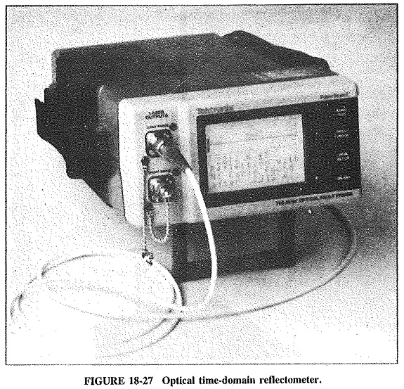
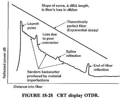
Because of the problems encountered with the power meter, another Fiber Optic Testing device which achieves higher reliability is used. This is the optical time-domain reflectometer, or OTDR (see Figure 18-27). The OTDR uses the reflective light backscattered (Rayleigh scattering) from the fiber. The reflective light is compared to a normal decaying light pulse from a light source focused through a beam splitter to produce a visual display on a CRT (see Figure 18-28) to determine splice and connector losses. As the light pulse is reflected back to the beam splitter, the time for complete pulse decay (5 ns/m) is displayed as a diagonal line starting at the top left and proceeding down to the lower right of the screen. Any changes in the backscattering process (splices,broken fiber, connector attenuation) appear as abrupt changes in the display. This evaluation method can analyze the following conditions:
-
Loss per unit length (measure before and after installation to determine stress bends, and so forth)
-
Splice and connector quality
-
Stress bends, bad splices, or faulty connectors
With the information gained from the OTDR, the engineer can determine whether the system budget requirements have been achieved; that is, does the power input minus the power losses equal the engineering requirements?. Power losses in fibers can be measured and calculated in two ways by the optical power meter. The first method is to measure the light attenuation of the uncut fiber, make the cut, install the connector, and remeasure using Equation (18-13).
![]()
where
P1 is the first measurement
P2 is the second measurement
L is the difference between the two cable lengths
The second method is to use a standard length of fiber as a reference and compare it to the cable being installed, using the power meter measurements in a manner similar to that described above.