Direct Testing of Circuit Breaker:
The Direct Testing of Circuit Breaker in a plant enables us to test under conditions largely representing those in actual network as well as tests of greater severity. The circuit breaker to be tested is subjected to the value of transient restriking voltage to which it is expected to be put in practice rather than testing it under most severe conditions. Value of the transient restriking voltage is adjusted by means of R, L, and C, the constants of the circuit.
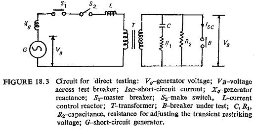
The Direct Testing of Circuit Breaker is shown in Fig. (18.3). After making the preliminary adjustments of the constants, etc. the contacts on the sequence switch are adjusted to get desired timings. The oscillographs are also adjusted and calibrated. The operations of test follow automatically by means of sequence switch as already mentioned.
The various tests carried out for circuit breakers are described below:
Making Capacity:
The master circuit breaker and the make switch are closed first, then the breaker under test is closed on a three-phase short circuit. The making current is already explained. This is a peak value of the first major loop of the current wave after the instant of contact make when current starts to flow. The measurement is made from the current zero line to the peak of the wave.
Breaking Capacity:
The master circuit breaker and the breaker under test are closed first, short circuit is applied by closing the make switch. The breaker under test is opened at desired moment and. the following values are measured from the oscillogram is already explained.
- Recovery voltage obtained during the test.
- Symmetrical breaking current.
- Asymmetrical breaking current.
- Amplitude factor, natural frequency and RRRV
Duty Cycle Tests:
Unless the rated operating duty as marked on the name plate differs from that specified, it shall consist of the following test duties.
Test duty (1) B-3′-B-3′-B at 10% of rated symmetrical breaking capacity.
Test duty (2) B-3′-B-3′-B at 30% of rated symmetrical breaking capacity.
Test duty (3) B-3′-B-3′-B at 60 % of rated symmetrical breaking capacity.
Test duty (4) B-3′-MB-3′-MB at not less than 100% of rated symmetrical breaking capacity and not less than 100% of rated making capacity. Test duty (4) may be performed as two separate duties as follows.
Test duty (4a) M-3′-M (Make test)
Test duty (4b) B-3′-B-3′-B (Break test)
Test duty (5) B-3′-B-3′–B at not less than 100 % rated asymmetrical breaking capacity.
B and M in the above duty cycle denote break and make operations respectively. MB denotes a making operation followed by a breaking operation without any intentional time lag. 3′ denotes the time in minutes between successive operations of an operating duty.
Short time Current Tests:
Good contact should be maintained in spite of forces produced by the short-circuit current so as to avoid welding. The heat generated by the short-circuit current over the period of the test (1 sec or 3 sec) should not cause damage to any insulation in contact with the current carrying parts. When the breaker has cooled down to the ambient temperature, it should be capable of carrying full-load current continuously without excessive temperature rise.
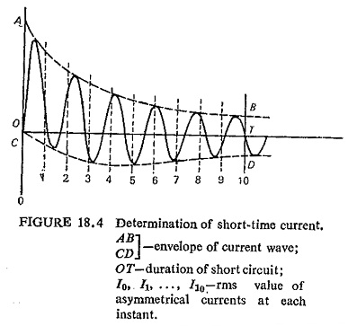
The breaker is tested for this by means of a separate high current and low voltage transformer. The current is measured by electromagnetic oscillograph. The equivalent steady rms value of current during a short circuit is evaluated as follows. Referring to Fig. (18.4) which illustrates a short-time current carrying test short-circuit duration is divided into ten equal parts. The asymmetrical rms value of the current at each of these eleven instants of time is calculated by the same method as that of breaking current. If these currents are I0, I1,….,I10. the equivalent steady rms value of current during the time or is given by Simpson formula.
![]()
Test Report:
Test report is issued under the seal of the testing authority as an authoritative statement on the performance of apparatus tested, irrespective of its compliance or non-compliance with standards.
Report of performance is a complete record of all tests done and may include development research and proving tests. The report includes details of the conditions under which the tests were made, the condition of the apparatus before and after tests and its performance during the tests. The tests which it covers will be those called for by the client (who may be a manufacturer or his customer) in addition to those which are necessary to prove the apparatus adequately.