Direct Synthesizer Block Diagram:
A Direct Synthesizer Block Diagram is a piece of apparatus in which multiples and submultiples of a single crystal oscillator frequency are combined by addition and/or subtraction to provide a very wide selection of stable output frequencies. The great advantage of such a system is that the accuracy and frequency stability of the output signal are equal to those of the crystal oscillator. The problems involved in the design and maintenance of a single-frequency oscillator of extreme precision and stability are much simpler than those associated with multi frequency oscillators. As crystals and techniques improve, the stability of this synthesizer is improved (if desired) simply by replacing the master oscillator. This is the reason why many synthesizers have master oscillators as separate modules.
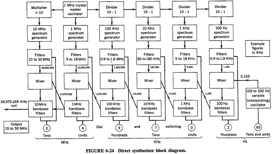
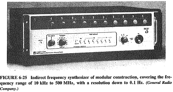
As shown by the Direct Synthesizer Block Diagram Figure 6-24 and the illustration of Figure 6-25, the direct synthesizer lends itself ideally to modular construction, with extra self-contained decades added as required. The circuit has also lent itself to the use of large-scale integration (LSI).
A convenient method of explaining the operation and reasons for certain circuit arrangements is to show how a typical frequency is selected. Let this frequency be 34,970.265 kHz, as shown in Figure 6-24. It will be seen immediately, for instance, that the kilohertz hundreds decade is not made to select 900 kHz in this case, but rather 1800 kHz. In fact, it is seen that all circuits except the first and last are made to select f + 9 units, where f units is the frequency one might have expected that decade to select. The interpolating oscillator selects f + 10 units. Coupled with the extra nine units added by every decade, this means that the signal fed by the megahertz units decade to the last mixer is 10 MHz larger than the dial shows. The last decade is made to provide 10 MHz less, and the correct frequency is obtained.
The interpolating oscillator is a highly stable RC oscillator whose frequency range, 100 to 200 Hz, is determined by two considerations. The operation of the decades ahead and the impossibility of covering the range from 0 to 100 Hz. In this instance, it is continuously tunable, with smallest divisions of 0.1 Hz, and is here made to provide 165.0 Hz because the frequency required ends in 65 Hz.
Each of the following decades consists of a divider, a spectrum generator whose function it is to provide all the harmonics from the ninth through to the eighteen of the frequency fed to it, a set of 10 narrow band filters to select any one of these harmonics by switching, a balanced mixer and a set of 10 band-pass filters, again selected by switching. Because the number of hertz hundreds required is 2, the first decade provides 11, which is 9 more, as outlined earlier. Together with the extra hertz hundred from the interpolating oscillator, this provides 10 extra hundreds, i.e., one extra thousand hertz for the next decade, which now has 1.265 kHz fed to its mixer, rather than 0.265 kHz. This process continues, with each succeeding decade receiving 10 more of the previous units than the dial indication shows, until eventually a frequency of 14,970.265 kHz is fed to the last mixer. Switching the last decade to 3, that is, 30 MHz, really brings only 20 MHz, and the final correct frequency, 34,970.265 kHz, is obtained.
The reason for such a complex addition procedure is quite simple. It is a function of the balanced mixers in each decade. Taking the hertz hundreds as an example, we find that the bandwidth of the mixer output circuit, any of the 10 bandpass filters, must be 100 Hz. This is so because the incoming frequency from the interpolating oscillator can be anywhere within the range from 100 to 200 Hz, depending on the frequency required. If the extra nine units were not added, the frequencies going into this mixer would be 65 Hz from the interpolating oscillator and 200 Hz from the filter above, yielding outputs of 265 and 135 Hz. These are fed to a filter whose bandpass stretches from 200 to 300 Hz, so that it might be pardoned for not suppressing the spurious frequency of 135 Hz. In the system as used the mixer receives 165 and 1100 Hz and puts out 1265 and 935 Hz. The filter now passes the 1200- to 1300-Hz range and is much better able to suppress the spurious frequency of 935 Hz.
The Direct Synthesizer Block Diagram is a good piece of equipment, but it does have some drawbacks. The first disadvantage is the possible presence of spurious frequencies generated by the many mixers used. Extensive filtering and extremely careful selection of operating frequencies are required, and it should be pointed out that the method shown here is but one of many. Spurious frequency problems increase as the output frequency range increases and channel spacing is reduced.
The second drawback is serious only in certain applications, such as military transceivers, in which an unstable output is better than none. Should the crystal oscillator in a direct synthesizer fail, no output will be available at all. In indirect synthesizers an output of reduced stability will be available under these conditions. The Direct Synthesizer Block Diagram may suffer unduly from so-called wide band phase noise.
The result of these drawbacks is that direct synthesizers have just about disappeared. The circuitry described above is still in widespread use, but as an integral part of an indirect synthesizer rather than an instrument in its own right.