Indirect Synthesizer:
Indirect Synthesizer: The required frequency range in most synthesizers nowadays is obtained from a variable voltage-controlled oscillator (VCO), whose output is corrected by comparison with that of a reference source. This inbuilt source is virtually a direct synthesizer. As shown in Figure 6-26, the phase comparator obtains an output from the VCO, compares it with the output of the stable reference source and produces a dc controlling output voltage whenever the VCO output is incorrect. The dc correcting voltage forms the basis of the automatic phase-correction (APC) loop, whose output is applied to a voltage-variable capacitance, which in turn pulls the VCO into line. The APC loop, or phase-locked loop can be quite similar to an automatic frequency correction (AFC) loop. The overall arrangement is known variously as a stabilized master oscillator (SMO), a phase-lock synthesizer or even as a VCO synthesizer with a phase-locked loop.

There are various possible arrangements for comparing the output of the VCO with that of the reference, via one or more phase-locked loops. The simplest one to think about is that in which all the circuits of the reference source (i.e., direct synthesizer) arc duplicated in the VCO. Whenever a frequency is selected, suitable capacitors/inductors are switched in to provide the VCO with an approximately correct frequency, which is finally corrected by the APC loop. Another possibility is to have each decade of the direct synthesizer drive its own SMO. Still another is to have a VCO that is switched in decade steps only, and whose frequency adjustment is sufficiently wideband to allow correction to any frequency within that decade frequency range.
An Indirect Synthesizer is a good deal more complex than a direct one. There are good reasons why it has outlasted the direct synthesizer.
The first reason has already been mentioned. It deals with the ability of the Indirect Synthesizer to provide an unlocked output, should the crystal oscillator fail. In some applications, such as commercial transmitters, this facility is a liability. In portable transceivers used by the military, police, and other similar users, this emergency facility is most desirable.
The second advantage of the Indirect Synthesizer is a major one and relates to reduced trouble with spurious frequencies, as compared with the direct synthesizer. As discussed in the preceding section, the various frequencies generated in the production of the wanted frequency in the direct synthesizer cannot be present in the output here, since that portion of the device is now used only for reference.
Finally, the short-term (milliseconds) stability of a crystal oscillator is not as good as that of a free-running oscillator designed with comparable care. The long-term stability of the crystal oscillator is better by far. The VCO represents a marriage, in which an oscillator that has an excellent short-term stability is controlled by an oscillator whose long-term stability is similarly excellent, and the result is the best of both worlds. The direct synthesizer by itself would produce rapid jittering in phase, which is interpreted as noise. Because the jitter is rapid, the noise can occupy a large bandwidth; hence the name wideband phase noise. Using the output of the VCO effectively overcomes the source of this noise, and long-term stability is guaranteed by comparison with the output of the crystal-derived frequency via the APC loop. With phase jitter thus minimized, a frequency synthesizer is said to have low residual FM.
The control functions in a majority of modern synthesizers, be they individual instruments or part of receivers or transmitters, are performed digitally. This applies especially to the control loop or loops. The receiver shown in Figure 6-18 features a very interesting synthesizer with digital control. Together with microprocessor control, digital frequency synthesis has the advantages of small bulk, flexibility, programmable channel selection, and excellent remote control facilities.
Functional Diagram of Communications Receiver Microprocessor Control:
Whereas frequency synthesizers are found mostly in communications equipment, and thus there was need to explain their operation in the preceding section, microprocessors belong more in the realm of computers In addition, they form a large subject of study on their own, and so in this section only their applications to receiver control will be discussed. It will be assumed that students understand the basics of microprocessor operation.
The application of microprocessor control to receivers (and also transmitters) arose out of the need for remote control, as well as the desire to increase operational flexibility and convenience. It was made possible by the advent of large-scale integration, which enabled microprocessors of small size and great power to be fitted conveniently into rebeivers, and the availability of frequency synthesizers, which avoided the need for manual tuning and calibration of receivers.
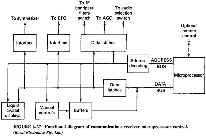
Figure 6-27 shows, in simplified form, the main microprocessor control functions built into the communications receiver of Figure 6-18. It is seen that, after receiving its instructions (by remote control or along the data bus from the manual controls), the microprocessor initiates an address sequence. The word or words in this sequence are decoded and applied to a number of key points in the receiver, which then generate the desired actions. One of the addresses is applied to a set of data latches (glorified flip-flops). These select the appropriate AGC function, the wanted IF bandpass filter from among the six provided, and the appropriate audio function (e.g., USB or LSB). The address is also applied to the manual controls, where appropriate voltages select the wanted channel, IF gain, form of frequency scanning, and so on. It is also applied to the liquid crystal displays, to ensure that the selected quantities are correctly indicated for the operator. Similarly, either on request by the microprocessor or because of the manual settings, other data latches operate the synthesizer interface and the BFO interface, adjusting their outputs to the desired values.
Microprocessor control very significantly increases the versatility of a communications receiver. To begin with, full remote control becomes available. This has many applications, such as switching between two distant receivers for best output under fading conditions, or even complete remote control of a coast radio station from a central point. Complex search and channel selection patterns can be stored in the microprocessor memory and used as required with very simple initiation procedures. Test routines can be stored and simply used as required.