IEEE 488 Bus Block Diagram:
The purpose of IEEE 488 BUS is to provide digital interfacing between programmable instruments. There are many instrumentation systems in which interactive instruments, under the command of a central controller, provide superior error-free results when compared with conventional manually operated systems.
Problems such as impedance mismatch, obtaining cables with proper connectors and logic level compatibility are also eliminated by designing the system around a bus-compatible instrument.
The basic structure of an IEEE 488 bus showing interfacing between interactive instruments is given in Fig. 6.29.
Every device in the system must be able to perform at least one of the roles, namely talker, listener or controller. A talker can send data to other devices via the bus. Some devices, such as programmable instruments, can both listen and talk.
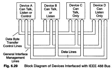
In the listen mode it may receive an instruction to make a particular measurement and in the talk mode it may send its measurand. A controller manages the operation of the bus system. It controls data gathering and transfer by designating which devices talk or listen as well as controlling specific actions within other devices.