Bus Zone Protection:
Bus Zone Protection includes, besides the bus itself the apparatus such as circuit breakers, disconnecting switches, instrument transformers and bus sectionalizing reactors, etc. Although bus zone faults are rare, experience shows that bus zone protection is highly desirable in large and important stations. Bus zone is more vulnerable to the effects of faults once it occurs for the following reasons:
- Concentration of fault MVA increases risk of considerable damage.
- Loss of bus zone would result in widespread supply interruption.
It is of utmost importance therefore that bus zone protection should be fast, stable and most reliable. Periodic testing is necessary to check the pickup of the relay on internal faults. It is the opinion of some experts that local bus protection should not be provided and the bus faults cleared by the backup relays at the neighboring stations, as the provision of local bus protection would certainly increase the risk of inadvertent tripping.
Where local bus protection is provided care is taken by providing two independent protective circuits, both of which must be satisfied before tripping can occur.
Bus Zone Faults:
Bus zone faults can generally be classified under one of the following headings.
- Failure of circuit breakers to interrupt fault current or failure to clear under through fault conditions.
- Insulation failure due to material deterioration.
- Flashover caused by prolonged and excessive overvoltages.
- Errors in the operation and maintenance of switchgear.
- Foreign objects accidentally falling across bus bars.
The clearing of a bus fault requires the opening of all the circuits branching from the faulted bus or bus section (except circuits having no backfeed).
Bus Backup Protection:
When no separate bus protection is provided but distance protection is provided for the feeders connected to the bus, it is possible ko cover the bus bars within zone 2 reach of the distance relays. It may however be noted that for small switchgear installations such a scheme may be quite satisfactory, whereas for large and important installations a separate bus zone protection may be provided.
Bus backup protection may also mean that in case the breaker fails to operate for a fault on the feeder then it must be regarded as a bus fault. It should then open all other breakers on that bus. Such a backup can be provided with appropriate time delay through a timer.
Differential Schemes of Bus Bar Protection:
It is based on simple circulating current principle that during normal load conditions or external fault conditions the sum of currents entering a bus equals the sum of those leaving. If the sum of these currents (for a given conductor) is not zero, it must be due to a short circuit either a ground fault or a phase-to-phase fault. Hence differential schemes can be applied for both these type of faults, the essential difference in the schemes being the method of connecting the CTs.
A simple differential protection of a bus section is shown in Fig. (6.31). A current in the relay indicates. a fault within the protected region and initiates opening of the generator breaker and each of the line breakers.
The main drawback with this type of differential protection is the difference in the magnetic conditions of the iron cored CTs which may result in false operation of the relay at the time of an external fault. Even with identical CTs having large iron cores to avoid the saturation with maximum fault currents the d.c. transient component presents difficulty because of its slow decay. Biasing of differential relays improves the stability considerably but is not a complete solution.
It can be seen that a high impedance bus differential relay can discriminate between internal and external faults better than the usual low-impedance relay. In;other words, the ratio of the relay current during’ an internal fault to relay current during an external fault is greater if the impedance of the relay is higher.
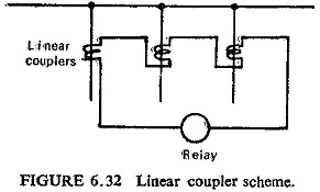
A special type of CT having no iron core also known as the linear coupler is sometimes employed to overcome the difficulties of an iron coned CT. In the case of a linear coupler the secondary voltage is proportional to the primary current, and the secondary windings of all couplers on the same bus section are connected in series to the relay as shown in Fig. (6.32). The sum of their voltage outputs is equal to the vector sum of the voltages in the circuits connected to the bus bars. Under normal and external fault conditions the voltages add up to zero. whereas for an internal fault there is a resultant voltage in the secondary circuit and the relay operates.
Frame Leakage Protection:
It is possible to design a station so that the faults which develop are mostly earth faults, by providing earthed metal barrier surrounding each conductor in the bus structure. With this arrangement every fault that might occur must involve a connection between a conductor and an earthed metal part. A somewhat less certain arrangement may be obtained in open construction by making spacing between adjacent conductors great compared to spacing over insulators to earth. Again faults that occur will almost certainly be from a conductor to supporting structure.
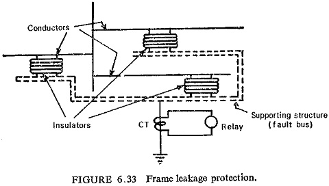
In each of the preceding cases the metal supporting structure also known as fault bus is earthed through a CT as shown in Fig. (6.33). A fault involving a connection between a conductor and the earth, i.e. supporting structure, will result in current flow through this CT and actuation of the relay connected to its secondary. Operation of this relay will result in tripping all breakers connecting equipment to the bus. Sometimes an impedance Z is connected in the earthing connection to limit the value of the short circuit current during line to earth fault.
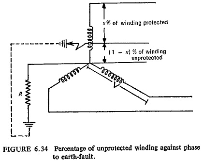
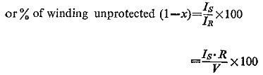
The value of the neutral earthing resistor and the amount of winding to be protected determines the relay fault setting. The usual practice is to protect 80-85% of alternator or transformer winding against earth fault. The remaining 15-20% from neutral end is left unprotected. It can be seen in Fig. (6.34) for phase-to earth-fault that the setting required from the differential protection is determined by the value of the neutral earthing resistor and also by the amount of winding to be protected. The earth-fault current IF is given by
![]()
This must be equal to the primary fault setting of the differential protection Is for minimum operating current.
Thus
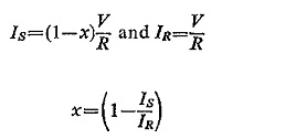
where
Is = Primary fault setting current.
IR = Earthing resistor current setting.
R = Earthing resistance.