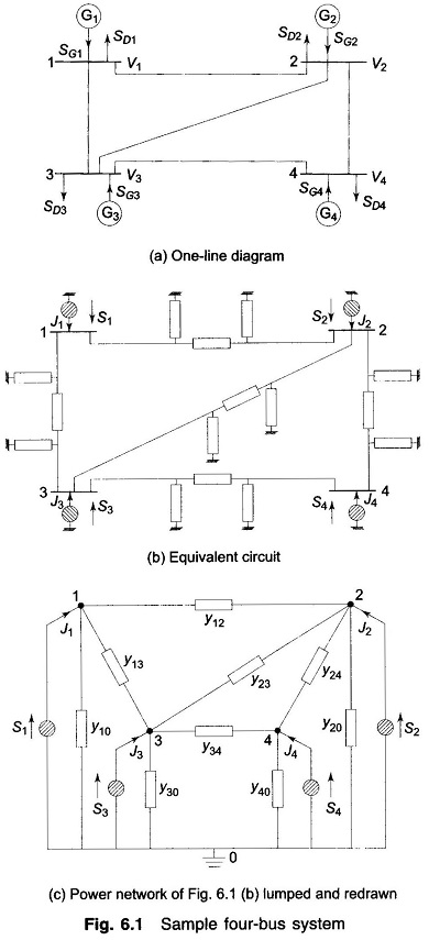
One Line Diagram of the 4 Bus System:
A power system comprises several buses which are interconnected by means of transmission lines. Power is injected into a bus from generators, while the loads are tapped from it. Of course, there may be buses with only generators and no-loads, and there may be others with only loads and no generators. Further, VAR generators may also be connected to some buses. The surplus power at some of the buses is transported via transmission lines to buses deficient in power. Figure 6.1a shows the One Line Diagram of the 4 Bus System with generators and loads at each bus.
To arrive at the network model of a power system, it is sufficiently accurate to represent a short line by a series impedance and a long line by a nominal- π model (equivalent-π may be used for very long lines). Often, line resistance may be neglected with a small loss in accuracy but a great deal of saving in computation time.
For systematic analysis, it is convenient to regard loads as negative generators and lump together the generator and load powers at the buses. Thus at the ith bus, the net complex power injected into the bus is given by
![]()
where the complex power supplied by the generators is
![]()
and the complex power drawn by the loads is
![]()
The real and reactive powers injected into the ith bus are then
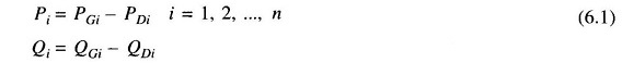
Figure 6.1b shows the network model of the sample power system prepared on the above lines. The equivalent power source at each bus is represented by a shaded circle. The equivalent power source at the ith bus injects current Ji into the bus. It may be observed that the structure of a power system is such that all the sources are always connected to a common ground node.
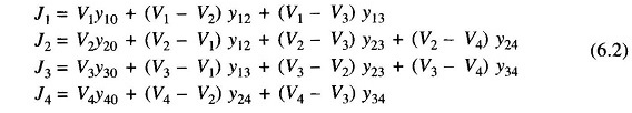
The network model of Fig. 6.1b has been redrawn in Fig. 6.1c after lumping the shunt admittances at the buses. Besides the ground node, it has four other nodes (buses) at which the current from the sources is injected into the network. The line admittance between nodes i and k is depicted by yik = yki. Further, the mutual admittance between lines is assumed to be zero.
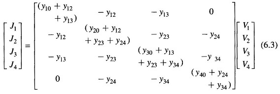
Applying Kirchhoff’s current law (KCL) at nodes 1, 2, 3 and 4, respectively, we get the following four equations:
Rearranging and writing in matrix form, we get
Equation (6.3) can be recognized to be of the standard form
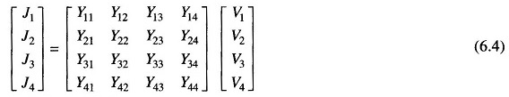
Comparing Eqs. (6.3) and (6.4), we can write
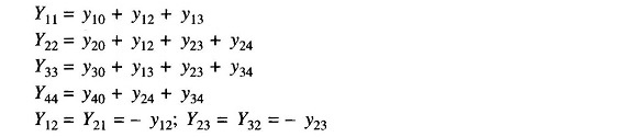
Each admittance yii (i = 1, 2, 3, 4) is called the self admittance (or driving point admittance) of node i and equals the algebraic sum of all the admittances terminating on the node. Each off-diagonal term yik (i, k = 1, 2, 3, 4) is the mutual admittance (transfer admittance) between nodes i and k and equals the negative of the sum of all admittances connected directly between these nodes. Further, yik = yki.
Using index notation, Eq. (6.4) can be written in compact form as

or, in matrix form
![]()
where YBUS denotes the matrix of bus admittance and is known as bus admittance matrix. The dimension of the YBUS matrix is (n x n) where n is the number of buses. [The total number of nodes are m = n + 1 including the ground (reference) node.]
As seen above, YBUS is a symmetric matrix, except when phase shifting transformers are involved , so that only n(n+1)/2 terms are to be stored for an n-bus system. Furthermore, Yik = 0 if buses i and k are not connected (e.g. Y14 = 0). Since in a power network each bus is connected only to a few other buses (usually to two or three buses), the YBUS of a large network is very sparse, i.e. it has a large number of zero elements. Though this property is not evident in a small system like the sample system under consideration, in a system containing hundreds of buses, the sparsity may be as high as 90%. Tinney and associates [22] at Bonnevile Power Authority were the first to exploit the sparsity feature of YBUS in greatly reducing numerical computations in load flow studies and in minimizing the memory required as only non-zero terms need be stored.
Equation (6.6) can also be written in the form
![]()
where
![]()
for a network of one line diagram of the 4 Bus System (four independent nodes)
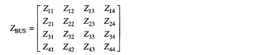
Symmetric YBUS yields symmetric ZBUS. The diagonal elements of ZBUS are called driving point impedances of the nodes, and the off-diagonal elements are called transfer impedances of the nodes. ZBUS need not be obtained by inverting YBUS. While YBUS is a sparse matrix, ZBUS is a full matrix. i.e., zero elements of YBUS become non-zero in the corresponding ZBUS elements.
It is to be stressed here that YBUS/ZBUS constitute models of the passive portions of the power network.
Bus admittance matrix is often used in solving load flow problem. It has gained widespread application owing to its simplicity of data preparation and the ease with which the bus admittance matrix can be formed and modified for network changes addition of lines, regulating transformers, etc. Of course, sparsity is one of its greatest advantages as it heavily reduces computer memory and time requirements. In contrast to this, the formation of a bus impedance matrix requires either matrix inversion or use of involved algorithms Furthermore, the impedance matrix is a full matrix.
Note: In the sample system of Fig. 6.1, the one line diagram of the 4 Bus System are numbered in an arbitrary manner, although in more sophisticated studies of large power systems, it has been shown that certain ordering of nodes produces faster convergence and solutions.