Single Line Diagram of Electrical System:
The function of an Structure of Electrical Power System is to connect the power station to the consumers’ loads by means of interconnected system of transmission and distribution networks. Therefore, an electric power system consists of three principal components : the power station, the transmission lines and the distribution systems. The transmission lines are the connecting link between the power station and the distribution systems. A distribution system connects all the individual loads in a given locality to the transmission lines. Fig. 3.1, shows the Single Line Diagram of Electrical System of a very simple Electrical Power System.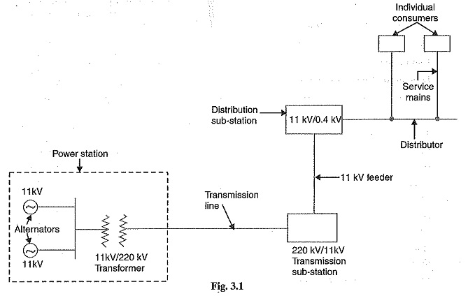
The power station generally houses two or more 3-phase alternators operated in parallel. Due to technical reasons, the generation voltage:is not very high ; it is usually 11 kV to 25kV. The power stations are located at favorable places, generally quite far away from the consumers. Owing to economical reasons, electric power has to be transmitted through transmission lines at a very high voltage. Therefore, voltage at the power station is stepped to a high value (say 220 kV) by the step-up transformer.
The electric power is carried by the transmission lines at this high voltage. At the outskirts of the city, this voltage is reduced considerably (say 11 kV) by a step-down transformer (also called transmission sub-station). The feeders carry the power to distribution sub-station. Feeders should not be tapped for direct supply. At the distribution sub-station, the step-down transformer reduces the voltage to 400 V (11kV/0.4 kV transformer — 400 V line voltage and 230 V phase voltage). Distributors are used to supply power to various consumers.
The following points may be noted :
1.For the sake of simplicity, we show the 3-phase circuit by a Single Line Diagram of Electrical System.
2.The 3-phase alternators at the power station are designed to produce balanced voltages.
Since a balanced 3 phase system is always solved as a single-phase circuit composed of one of the three lines and a neutral return, it is seldom necessary to show more than one phase and the neutral return when drawing a diagram of the circuit. Often the diagram is simplified further by omitting the neutral wire and by indicating the component parts by standard symbols rather than by their equivalent circuits. Such a simplified diagram of an electric power system is called Single Line Diagram of Electrical System.
3.In an actual electric power system, there are a number of protective devices (fuses, circuit breakers, relays etc.) and other equipment. The amount of information included in the Single Line Diagram of Electrical System depends on the purpose for which the diagram is intended. For example, in this chapter, we are to make load study. For this purpose, circuit breakers, relays etc. are unimportant and are omitted in the diagram shown in Fig. 3.1.
4.The power demanded by the consumers is supplied by the power station through the transmission and distribution networks. As the consumers’ load demand changes, the power supply by the power station changes accordingly.