Single Line to Ground Fault:
Figure 11.4 shows a Single Line to Ground Fault at F in a power system through a fault impedance Zf. The phases are so labelled that the fault occurs on phase a.
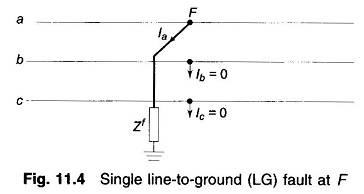
At the fault point F, the currents out of the power system and the Single Line to Ground Fault are constrained as follows:
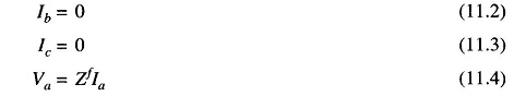
The symmetrical components of the fault currents are
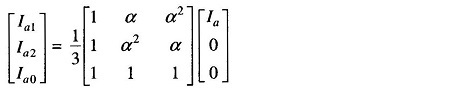
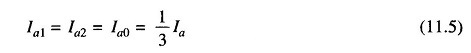
from which it is easy to see that
Expressing Eq.(11.4) in terms of symmetrical components, we have
![]()
As per Eqs. (11.5) and (11.6) all sequence currents are equal and the sum of sequence voltages equals 3Zf Ia1. Therefore, these equations suggest a series connection of sequence networks through an impedance 3Zf as shown in Figs. 11.5a and b.
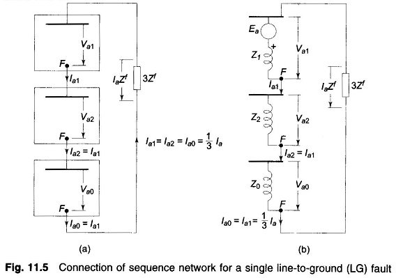
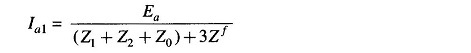
In terms of the Thevenin equivalent of sequence networks, we can write from Fig. 11.5b.
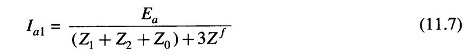
Fault current Ia is then given by
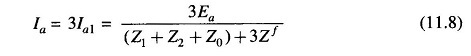
The above results can also be obtained directly from Eqs. (11.5) and (11.6) by using Va1, Va2, and Va0 from Eq. (11.1). Thus
![]()
or
![]()
or
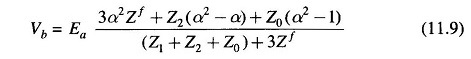
The voltage of line b to ground under fault condition is
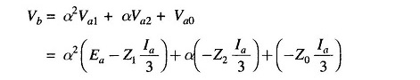
Substituting for Ia from Eq. (11.8) and reorganizing, we get
The expression for Vc can be similarly obtained.
Fault Occurring Under Loaded Conditions:
When a fault occurs under balanced load conditions, positive sequence currents alone flow in power system before the occurrence of the fault. Therefore, negative and zero sequence networks are the same as without load. The positive sequence network must of course carry the load current. To account for load current, the synchronous machines in the positive sequence network are replaced by subtransient, transient or synchronous reactances (depending upon the time after the occurrence of fault, when currents are to be determined) and voltages behind appropriate reactances. This change does not disturb the flow of prefault positive sequence currents. This positive sequence network would then be used in the sequence network connection of Fig. 11.5a for computing sequence currents under fault.
In case the positive sequence network is replaced by its Thevenin equivalent as in Fig. 11.5b, the Thevenin voltage equals the prefault voltage V°f at the fault point F (under loaded conditions). The Thevenin impedance is the impedance between F and the reference bus of the passive positive sequence network (with voltage generators short circuited).
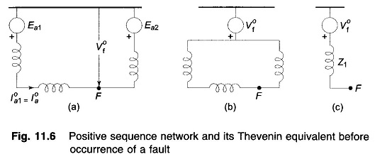
This is illustrated by a two machine system in Fig. 11.6. It is seen from this figure that while the prefault currents flow in the actual positive sequence network of Fig. 11.6a, the same do not exist in its Thevenin equivalent network of Fig. 11.6b. Therefore, when the Thevenin equivalent of positive sequence network is used for calculating fault currents, the positive sequence currents within the network are those due to fault alone and we must superimpose on these the prefault currents. Of course, the positive sequence current into the fault is directly the correct answer, the prefault current into the fault being zero.
The above remarks are valid for the positive sequence network, independent of the type of fault.