Square Law Detector Circuit and Working Principle:
The square law detector circuit is used for demodulating modulated signal of small amplitude (i.e., below 1 V) so that the operating region may be restricted to the nonlinear portion of the V-I characteristics of the device.
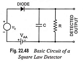
Figure 22.48 shows the circuit of a square law detector. It may be observed that the circuit is very similar to the square law modulator. The only difference lies in the filter circuit. The square law modulator uses a bandpass filter whereas the square law detector makes use of a low-pass filter.
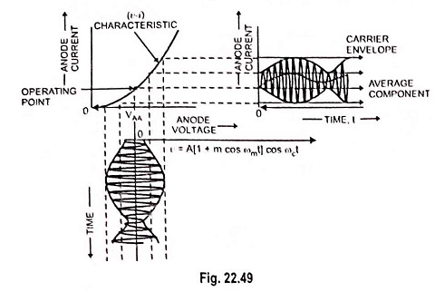
In the circuit, the dc supply voltage VAA is used to get the fixed operating point in the nonlinear region of the diode V-I characteristic. Since, the operation is limited to the nonlinear region of the diode characteristics, the lower half portion of the modulated waveform is compressed. This produces envelope applied distortion. Because of this, the average value of the diode current is no longer constant, rather it varies with time as indicated in Fig. 22.49.
The distorted output diode current is expressed by the nonlinear v-i relationship (i.e., square law) as
![]()
where v is the input modulated voltage
AM wave may be expressed as
![]()
Substituting the value of v from Eq. (22.59) in Eq. (22.58), we have
![]()
Now, if above equation is expanded, then we observe the presence of terms of frequencies like 2ωc, 2(ωc ± ωm), ωm and 2ωm besides the input frequency terms.
Hence, this diode current i containing all these frequency terms is passed through a low-pass filter which allows to pass the frequencies below or up to modulating frequency ωm and rejects the other higher frequency components. Thus, the modulating or baseband signal with frequency ωm is recovered from the input modulated signal.