AF Sine and Square Wave Generator:
The block diagram of an AF Sine and Square Wave Generator audio oscillator is illustrated in Fig. 8.4.
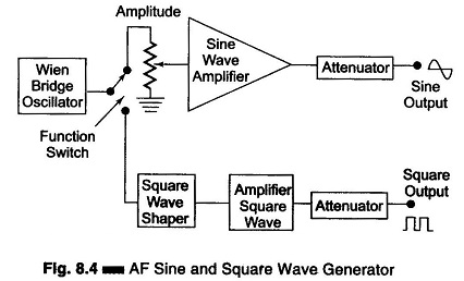
The signal generator is called an oscillator. A Wien bridge oscillator is used in this generator. The Wien bridge oscillator is the best for the audio frequency range. The frequency of oscillations can be changed by varying the capacitance in the oscillator. The frequency can also be changed in steps by switching in resistors of different values.
The output of the Wien bridge oscillator goes to the function switch. The function switch directs the oscillator output either to the sine wave amplifier or to the square wave shaper. At the output, we get either a square or sine wave. The output is varied by means of an attenuator.
The instrument generates a frequency ranging from 10 Hz to 1 MHz, continuously variable in 5 decades with overlapping ranges. The output sine wave amplitude can be varied from 5 mV to 5 V (rms).The output is taken through a push-pull amplifier. For low output, the impedance is 600Ω. The square wave amplitudes can be varied from 0 – 20 V (peak). It is possible to adjust the symmetry of the square wave from 30 – 70%. The instrument requires only 7 W of power at 220 V – 50 Hz.
The front panel of a signal generator consists of the following.
- Frequency selector – It selects the frequency in different ranges and varies it continuously in a ratio of 1 : 11. The scale is non-linear.
- Frequency multiplier – It selects the frequency range over 5 decades, from 10 Hz to 1 MHz.
- Amplitude multiplier – It attenuates the sine wave in 3 decades, x 1, x 0.1 and x 0.01.
- Variable amplitude – It attenuates the sine wave amplitude continuously.
- Symmetry control – It varies the symmetry of the square wave from 30% to 70%.
- Amplitude – It attenuates the square wave output continuously.
- Function switch – It selects either sine wave or square wave output.
- Output available – This provides sine wave or square wave output.
- Sync – This terminal is used to provide synchronisation of the internal signal with an external signal.
- On-Off Switch.