Function Generator Block Diagram:
A Function Generator Block Diagram produces different waveforms of adjustable frequency. The common output waveforms are the sine, square, triangular and sawtooth waves. The frequency may be adjusted, from a fraction of a Hertz to several hundred kHz.
The various outputs of the generator can be made available at the same time. For example, the generator can provide a square wave to test the linearity of an amplifier and simultaneously provide a sawtooth to drive the horizontal deflection amplifier of the CRO to provide a visual display.
Capability of Phase Lock:
The function generator can be phase locked to an external source. One function generator can be used to lock a second function generator, and the two output signals can be displaced in phase by adjustable amount.
In addition, the fundamental frequency of one generator can be phase locked to a harmonic of another generator, by adjusting the amplitude and phase of the harmonic, almost any waveform can be generated by addition.
The function generator can also be phase locked to a frequency standard and all its output waveforms will then have the same accuracy and stability as the standard source.
The Function Generator Block Diagram is illustrated in Fig. 8.5. Usually the frequency is controlled by varying the capacitor in the LC or RC circuit. In this instrument the frequency is controlled by varying the magnitude of current which drives the integrator. The instrument produces sine, triangular and square waves with a frequency range of 0.01 Hz to 100 kHz.
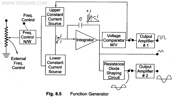
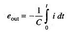
The frequency controlled voltage regulates two current sources. The upper current source supplies constant current to the integrator whose output voltage increases linearly with time, according to the equation of the output signal voltage.
An increase or decrease in the current increases or decreases the slope of the output voltage and hence controls the frequency.
The voltage comparator multivibrator changes states at a pre-determined maximum level of the integrator output voltage. This change cuts off the upper current supply and switches on the lower current supply.
The lower current source supplies a reverse current to the integrator, so that its output decreases linearly with time. When the output reaches a predetermined minimum level, the voltage comparator again changes state and switches on the upper current source.
The output of the integrator is a triangular waveform whose frequency is determined by the magnitude of the current supplied by the constant current sources.
The comparator output delivers a square wave voltage of the same frequency. The resistance diode network alters the slope of the triangular wave as its amplitude changes and produces a sine wave with less than 1% distortion.