Automatic Frequency Control Block Diagram:
Automatic frequency control: As previously we see, the heart of an AFC circuit is a frequency-sensitive device, such as the phase discriminator, which produces a dc voltage whose amplitude and polarity are proportional to the amount and direction of the local oscillator frequency error. This dc control voltage is then used to vary, automatically, the bias on a variable-reactance device, whose output capacitance is thus changed. This variable capacitance appears across the (first) local oscillator coil, and the frequency of this variable-frequency oscillator (VFO), is automatically kept from drifting with temperature, line voltage changes or component aging. A Automatic Frequency Control Block Diagram system is shown in Figure 6-22.
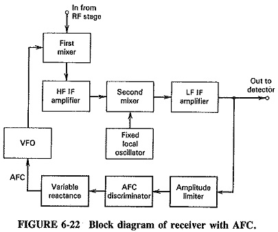
It is worth noting that the number of extra stages required to provide Automatic Frequency Control Block Diagram is much smaller in a double-conversion receiver than in the stabilized reactance modulator, since most of the functions required are already present. Not all receivers require Automatic Frequency Control Block Diagram, especially not synthesized ones. Those that benefit most from its inclusion are undoubtedly non-synthesized SSB receivers, whose local oscillator stability must be exceptionally good to prevent drastic frequency variations in the demodulated signal.
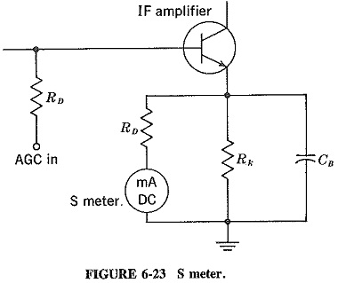
Metering: A built-in meter with a function switch is very often provided. It is very helpful diagnosing any faults that may occur, since it measures voltages at key points in the receiver. One of the functions (sometimes the sole function) of this meter is to measure the incoming signal strength. It is then called an S meter, and very often reads the collector current of an IF amplifier to which AGC is applied, as shown in Figure 6-23. Since this collector current decreases as the AGC goes up, the meter has its zero on the right-hand side. The S meter may sometimes be in an unbalanced bridge and hence forward-reading. The calibration of the meter is likely to be quite arbitrary because of the great variation of the sensitivity of the receiver through the bands, especially if there is a sensitivity control or adjustable delayed AGC.
A receiver with an S meter is definitely more versatile than one without. Not only can tuning to a wanted signal now be more accurate, but the receiver can also be used as a relative signal-strength meter and even as the detector for an RF impedance bridge. Moreover, it can also be used for applications such as tuning individually to the various sideband frequencies of an FM signal. This can determine the presence of those components and demonstrate the disappearance of the carrier for certain values of modulation index, from which readings deviation and linearity of the FM source may be determined. As we see already, microprocessor-controlled receivers can have very elaborate metering, with digital display of many functions, including the relative signal strength.
FM and SSB reception: Many receivers have provision for the reception of FM, either the narrow band FM used by mobile networks or the high-quality broadcast transmissions in the 88- to 108-MHz band. To allow FM reproduction, a receiver requires broadband IF stages, an FM demodulator and an amplitude limiter.
Most present-day communications receivers have facilities for single-sideband reception. Basically this means that a product detector must be provided, but it is also very helpful if there is an Automatic Frequency Control Block Diagram system present, as well as variable selectivity (preferably with crystal or mechanical filters), since the bandwidth used for SSB is a good deal narrower than for ordinary AM.
Diversity reception: Diversity reception is not so much an additional circuit in a communications receiver as a specialized method of using such receivers. There are two forms, space diversity and frequency diversity.
Although AGC helps greatly to minimize some of the effects of fading, it cannot help when the signal fades into the noise level. Diversity-reception systems make use of the fact that although fading may be severe at some instant of time, some frequency, and some point on earth, it is extremely unlikely that signals at different points or different frequencies will fade simultaneously.
Both systems are in constant use, by communications authorities, commercial point-to-point links and the military. In space diversity, two or more receiving antennas are employed, separated by about nine or more wavelengths. There are as many receivers as antennas, and arrangements are made to ensure that the AGC from the receiver with the strongest signal at the moment cuts off the other receivers. Thus only the signal from the strongest receiver is passed to the common output stages.
Frequency diversity works in much the same way, but now the same antenna is used for the receivers, which work with simultaneous transmissions at two or more frequencies. Since frequency diversity is more wasteful of the frequency spectrum, it is used only where space diversity cannot be employed, such as in restricted spaces where receiving antennas could not have been separated sufficiently. Ship-to-shore and ship-to-ship communications are the greatest users of frequency diversity at HF.
Both systems are known as double-diversity systems, in that there are two receivers, employed in a diversity pattern. Where conditions are known to be critical, as in tropospheric scatter communications, quadruple diversity is used. This is a space-diversity system which has receiver arrangements as just described, with two transmitters at each end of the link arranged in the same way as the receivers. This ensures that signals of adequate quality will be received under even the worst possible conditions.
There is one snag that applies to diversity systems and limits their use in voice communications. Since each signal travels over a slightly different path, the audio output will have a phase difference when compared with that of the other receiver(s). As a result, diversity reception is used very often for telegraph or data transmission (i.e., pulses): however, present diversity systems for voice communications leave much to be desired, unless some form of pulse modulation is employed.