Automatic Block Signalling System in Railways:
The purpose of automatic block signalling system in railways is to keep trains apart but permit spacing as close as safety permits. For optimum utilization of track capacity with utmost safety, automatic power-operated signalling systems are employed. Power operation also facilitates effective interlocking which reduces reliance upon human factors to the minimum. The signalling may be with semaphores arms, coloured lights or a combination of both. With semaphores or movable arms a lamp is usually so placed that, as the arm moves to one or two more positions, coloured lenses are shifted in front of the lamp to provide colour indications to the passing engine crew to correspond to the indication of the arms. Colour light signals use lamps that are brilliant enough to be seen in the brightest daylight.
The rail track is divided in blocks. A block is a length of track which is controlled or protected by a signal at the entering end. A block system is a series of consecutive blocks and each block is insulated from the adjacent block.
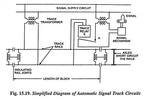
Automatic block signalling systems are operated by the presence of a train in the block. Automatic signals may employ either battery current or ac supply. The track circuits are energized by power between 2 and 8 volts either alternating or direct current. The rails at each end of the block are cut and connected by insulated joints. There is sufficient insulation in the wood ties so that the rails constitute conductors in a closed circuit with signal power supply at one end and a relay at the other end to actuate the signal (Fig. 15.19). When a train passes the insulating joints, the axles short circuit the rails and causes the relay to drop.
Advantages:
An advantage of this automatic block signalling arrangement is that a broken rail or a failure of power will also cause the relay to drop and provide a stop-and-proceed indication to the signal. Track relay R holds contact A closed when the relay is energised and allows it to open by gravity if for any reason the relay is de-energized. If ac power is used, the relay is a frequency type, usually 50 or 100 Hz, so if it should be energized at a lower frequency than that for which it is designed to operate, it will open its contacts, causing the signal to go to stop position. The source of energy is of as low voltage as practicable, to prevent operation in the event of short circuit by the train is not complete— and if there should be stray currents present.
DC is used where tracks are free from stray currents from adjacent traction systems. AC operated system is employed when there is a possibility of stray currents or where the track is employed for return current. In the latter case, the blocks are coupled across the insulated joints by impedance bonds. Their function is to permit the flow of traction current around the insulated joints by offering low resistance to it and offer high impedance to the signalling current. An impedance bond consists of a massive laminated iron core carrying a few turns of heavy copper. Two end terminals are connected to the two rails and the mid-point or neutral is brought out which is connected to a similar bond beyond the insulated joint.
When the track is unoccupied, the relay circuit is completed, via the two rails and a clear signal is hoisted. When a train enters the section, its axles short circuit the rails and causes the relay to drop. “Track occupied” signal is hoisted as long as the train is in the section.
