Automatic Voltage Control:
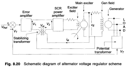
Automatic Voltage Control – Figure 8.20 gives the schematic diagram of an automatic voltage regulator of a generator. It basically consists of a main exciter which excites the alternator field to control the output voltage. The exciter field is automatically controlled through error e = Vref – VT, suitably amplified through voltage and power amplifiers. It is a type-0 system which requires a constant error e for a specified voltage at generator terminals.
The block diagram of the system is given in Fig. 8.21. The function of important components and their transfer functions is given below:
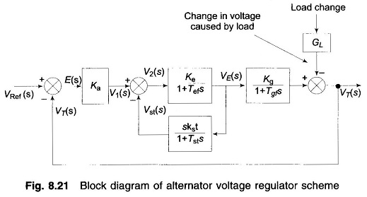
Potential transformer: It gives a sample of terminal voltage VT.
Differencing device: It gives the actuating error
![]()
The error initiates the corrective action of adjusting the alternator excitation. Error wave form is suppressed carrier modulated, the carrier frequency being the system frequency of 50 Hz.
Error amplifier: It demodulates and amplifies the error signal. Its gain is Ka.
SCR power amplifier and exciter field: It provides the necessary power amplification to the signal for controlling the exciter field. Assuming the amplifier time constant to be small enough to be neglected, the overall transfer function of these two is

where
- Tef is the exciter field time constant.
Alternator: Its field is excited by the main exciter voltage vE. Under no load it produces a voltage proportional to field current. The no load transfer function is

where
- Tgf = generator field time constant.
The load causes a voltage drop which is a complex function of direct and quadrature axis currents. The effect is only schematically represented by block GL. The exact load model of the alternator is beyond the scope of this book.
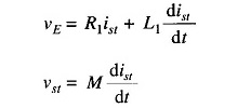
Stabilizing transformer: Tef and Tgf are large enough time constants to impair the system’s dynamic response. It is well known that the dynamic response of a control system can be improved by the internal derivative feedback loop. The derivative feedback in this system is provided by means of a stabilizing transformer excited by the exciter output voltage vE. The output of the stabilizing transformer is fed negatively at the input terminals of the SCR power amplifier. The transfer function of the stabilizing transformer is derived below. Since the secondary is connected at the input terminals of an amplifier, it can be assumed to draw zero current. Now
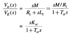
Taking the Laplace transform, we get
Accurate state variable models of loaded alternator around an operating point are available in literature using which optimal voltage regulation schemes can be devised.