Fully Automatic Digital Instrument:
Fully Automatic Digital Instrument – A multimeter with automatic polarity indication, automatic zero correction and automatic ranging (of course coupled with automatic decimal point indication) only needs a signal applied to its input, and a command as to what quantity (Vdc, Vac, I or R) to measure; it does all the rest itself.
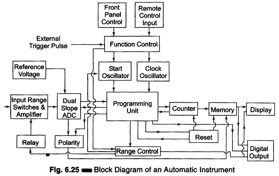
The digital part of a typical instrument is organized so as to produce a display or a digital output signal, as shown in Fig. 6.25. Before a measurement can begin, the functions of the instrument must be set, that is, we must select the quantity to be measured (e.g. voltage), the ranging mode (automatic or manual), and the start mode (internal or with an external trigger signal). This can be done by the front panel controls, or via a remote control input. In both cases, the signals are fed to the function control unit, while the information on ranging is passed to the range control unit.
Let us assume that in the instrument in question, the ADC is of the dual slope integration type, and that a choice can be made between the combinations given in Table 6.1.
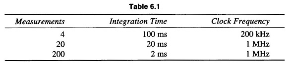
It will be clear that as the number of measurements per second increases, the integration time must be reduced and that it is useful to increase the clock frequency at the same time to maintain good resolution. To select the desired combination, information on the number of measurements per second must be fed to the start oscillator and clock oscillator. The latter constantly supplies clock pulses to the programming unit. The former is free running when the DVM is set for internal start, but it waits for an external trigger signal when the DVM is set for external control. Let us now follow (see Fig. 6.25) the various steps involved in the performance of a measurement, for the case that the instrument is set for automatic ranging and external triggering.
An incoming trigger pulse causes the start oscillator to deliver a pulse to the programming unit, and a measurement is started. The programming unit starts both the counter and the ADC. The ADC is connected to the input. The counter counts the clock pulses to determine the integration time and sends two signals back to the programming unit, one just before the end of the integration period, and the other at the end of this period. The first signal is used by the programming unit to activate the polarity detector, which determines the polarity of the integrated signal, while the second serves to switch the ADC input from the reference signal. At the same time, the counter is reset to zero and starts counting the down integration time of the ADC until it is stopped by the zero-detector signal of the ADC. At that moment, the programming unit compares the counter reading with the automatic ranging limits, and passes an up or down signal to the range control, if necessary. This unit switches the input range switches via a relay and triggers the start oscillator for a new measurement in a more sensitive or less sensitive range. In the meantime, the programming unit will also have reset the counter. This process continues until a measurement which is within the automatic ranging limits has been made.
The programming unit then transfers the new data from the counter to the memory, together with the polarity information so as to make them available to the display unit and the digital output. Finally, the programming unit delivers a transfer pulse to the digital output, to warn an instrument connected to this output (e.g. a printer) that new data has been made available.