Three phase Fully Controlled Rectifier Control of DC Separately Excited Motor:
Three phase Fully Controlled Rectifier Control (6 pulse) fed separately excited dc motor drive is shown in Fig. 5.32(a). Thyristors are fired in the sequence of their numbers with a phase difference of 60° by gate pulses of 120°duration. Each thyristor conducts for 120, and two thyristors conduct at a time—one from upper group (odd numbered thyristors) and the other from lower group (even numbered thyristors) applying respective line voltage to the motor.
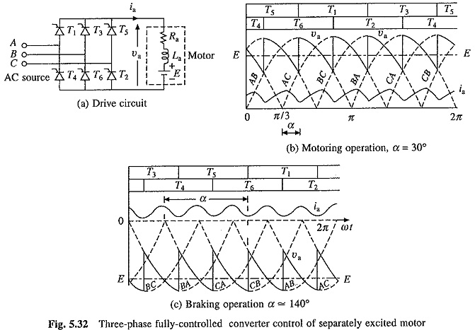
Transfer of current from an outgoing to incoming thyristor can take place when the respective line voltage is of such a polarity that not only if forward biases the incoming thyristor, but also leads to the reverse biasing of the outgoing when incoming turns-on. Thus, firing angle for a thyristor is measured from the instant when the respective line voltage is zero and increasing. For example, the transfer of current from thyristor T5to thyristor T1 can occur as long as the line voltage vAC is positive. Hence, for thyristor T1, firing angle α is measured from the instant vAC = 0 and increases as shown in Figs. 5.32(b) and (c).
If line voltage vAB is taken as the reference voltage, then
where Vm is the peak of line voltage.
Motor terminal voltage and current waveforms for continuous conduction are shown in Figs. 5.32(b) and (c) for motoring and braking operations, respectively. Devices under conduction are also shown in the figure. The discontinuous conduction is neglected here because it occurs is a narrow region of its operation. For the motor terminal voltage cycle from α + π/3 to α + 2π/3 (from Figs. 5.32(b) and (c)).
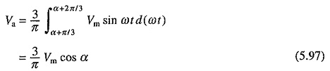
From Eqs. (5.7), (5.8), (5.79) and (5.97)
![]()
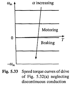
When discontinuous conduction is ignored, speed-torque curves of Fig. 5.33 are obtained. The Va vs α curve has same nature as shown in Fig. 5.28(a) for single-phase case. Consequently, drive operates in quadrants I and IV.
Three Phase Half Controlled Rectifier Control of DC Separately Excited Motor:
For rectifier circuit, shown in Fig. 5.25(d), under continuous conduction
![]()
From Eqs. (5.7), (5.8), (5.79) and (5.99)
![]()
Va vs α curve has same nature as shown in Fig. 5.31(a). Consequently, drive operates only in quadrant I.