Single Phase Fully Controlled Rectifier Control of DC Motor:
The Single Phase Fully Controlled Rectifier Control of DC Motor is shown in Fig. 5.26(a). Motor is shown by its equivalent circuit. Field supply is not shown. When field control is required, field is fed from a controlled rectifier, otherwise from an uncontrolled rectifier. The ac input voltage is defined by
![]()
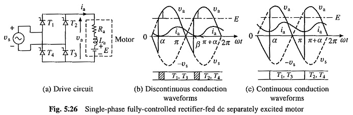
In a cycle of source voltage, thyristors T1 and T3 are given gate signals from α to π, and thyristors T2 and T4 are given gate signals from (π + α) to 2π. When armature current does not flow continuously, the motor is said to operate in discontinuous conduction. When current flows continuously, the conduction is said to be continuous. The drive under consideration, predominantly operates in discontinuous conduction. Discontinuous conduction has several modes of operation. The approximate, but a simple, method of analysis is obtained when only the dominant mode of discontinuous conduction is taken into account. The motor terminal voltage and current waveforms for the dominant discontinuous conduction and continuous conduction modes are shown in Figs. 5.26(b) and (c).
In discontinuous conduction mode of Single Phase Fully Controlled Rectifier Control of DC Motor, current starts flowing with the turn-on of thyristors T1 and T3 at ωt = α. Motor gets connected to the source and its terminal voltage equals vs. The current, which flows against both, E and the source voltage after ωt = π, falls to zero at β. Due to the absence of current T1 and T3 turn-off. Motor terminal voltage is now equal to its induced voltage E. When thyristors T2 and T4 are fired at (π + α), next cycle of the motor terminal voltage va starts.
In continuous conduction mode of Single Phase Fully Controlled Rectifier Control of DC Motor, a positive current flows through the motor, and T2 and T4 are in conduction just before α. Application of gate pulses turns on forward biased thyristors T1 and T3 at α. Conduction of T1 and T3 reverse biases T2 and T4 and turns them off. A cycle of va is completed when T2 and T4 are turned-on at (π + α) causing turn-off of T1 and T3.
Since armature current is is not perfect dc, the motor torque fluctuates. Since torque fluctuates at a frequency of 100 Hz, motor inertia is able to filter out the fluctuations, giving nearly a constant speed and rippleless E.
Discontinuous Conduction:
In a Single Phase Fully Controlled Rectifier Control of DC Motor terminal voltage va, the drive operates in two intervals (Fig. 5.26(b)):
- Duty interval (α ≤ ωt ≤ β) when motor is connected to the source and va = vs.
- Zero current interval (β ≤ ωt ≤ π + α) when ia = 0 and va = E.
Drive operation is described by the following equations: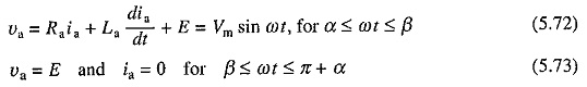
Solution of Eq. (5.72) has two components—one due to the ac source (Vm/Z) sin (ωt – Φ), and other due to back emf ( – E/Ra). Each of these components has in turn a transient component. Let these be represented by a single exponent K1e-t/τa, then
![]()
where
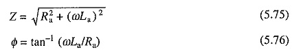
and τa is given by Eq. (5.25).
Constant K1 can be evaluated subjecting Eq. (5.74) to the initial condition ia(α) = 0. Substituting value of K1 so obtained in Eq. (5.74) yields
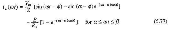
Since ia(β) = 0, from Eq. (5.77)

β can be evaluated by iterative solution of Eq. (5.78).
Since voltage drop across the armature inductance due to dc component of armature current is zero
![]()
where Va and la are respectively dc components of armature voltage and current respectively. From Fig. 5.26(6)
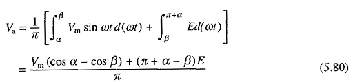
Armature current consists of dc component Ia and harmonics. When flux is constant, only dc component produces steady torque. Harmonics produce alternating torque components, the average value of which is zero. Therefore, motor torque is still given by Eq. (5.7). From Eqs. (5.7), (5.8), (5.79) and (5.80)

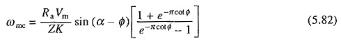
Boundary between continuous and discontinuous conduction is reached when β = π + α. Substituting β = π + α in Eq. (5.78) gives the critical value of speed ωmc which separates continuous conduction from discontinuous conduction for a given α as
Continuous Conduction:
From Fig. 5.26(c)
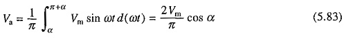
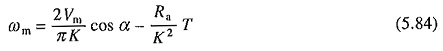
From Eqs. (5.7), (5.8), (5.79) and
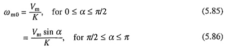
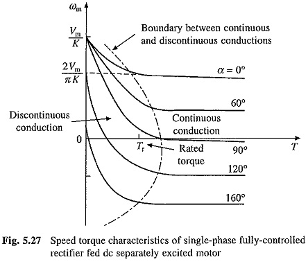
Speed torque curves for the drive are shown in Fig. 5.27. The ideal no load operation is obtained when Ia = 0. When both thyristor pairs (T1, T3) and (T2, T4) fail to fire, Ia will be zero. This will happen when E > vs throughout the period for which tiring pulses are present. Therefore, when α < π/2, E should be greater or equal to Vm and when α > π/2, E should be greater or equal to Vm sin ωt. Therefore, no load speeds are given by
Maximum average terminal voltage (2Vm/π) is chosen equal to the rated motor voltage. ideal no load speed of the motor when fed by a perfect direct voltage of rated value will then be (2Vm/πK). It is interesting is note that the maximum no load speed with rectifier control is (π/2) times this value. Boundary between continuous and discontinuous conduction is shown by dotted line (Fig. 5.27). For torques less than rated, a low power drive mainly operates in discontinuous conduction. In continuous conduction, the speed-torque characteristics are parallel straight lines, whose slope, according to (5.84), depends on the armature circuit resistance Ra. Effect of discontinuous conduction is to make speed regulation poor. This behavior can be explained from waveforms of Figs. 5.26(b) and (c). In continuous conduction, for a given α, any increase in torque causes ωm and E to drop so that Ia and T can increase. Average terminal voltage Va remains constant. In discontinuous conduction, any increase in torque and accompanied increase in Ia causes β to increase and Va to drop. Consequently, speed drops by a larger amount.
The drive operates in quadrants I (forward motoring) and IV (reverse regenerative braking). These operations can be explained as follows:
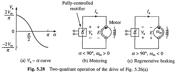
From Eq. (5.84), under the assumption of continuous conduction, dc output voltage of rectifier varies with α as shown in Fig. 5.28(a). When working in quadrant I, ωm is positive and α ≤ 90°; and polarities of Va and E are shown in Fig. 5.28(b). For positive Ia this causes rectifier to deliver power and the motor to consume it, thus giving forward motoring. Polarities of E, Ia and Va for quadrant IV operation are shown in Fig. 5.28(c). E has reversed due to reversal of ωm. Since Ia is still in same direction, machine is working as a generator producing braking torque. Further due to α > 90°, Va is negative, suggesting that the rectifier now takes power from dc terminals and transfers it to ac mains. This operation of rectifier is called inversion and the rectifier is said to operate as an inverter. Since generated power is supplied to the source in this operation, it is regenerative braking.
Two quadrant operation capability of the drive can be utilized only with overhauling loads or other active loads which can drive the motor in reverse direction. In a normal two quadrant operation of a motor one needs forward motoring (quadrant I) and forward braking (quadrant II) which cannot be provided by the drive of Fig. 5.26(a).