Instrument Transformers – Definition, Types and Errors:
AC type protective relays are actuated by current and voltage supplied by current and potential (or voltage) transformers, known as instrument transformers. The main function of instrument transformers are:
- To provide insulation against the high voltage of the power circuit and to protect the apparatus and the operating personnels from contact with the high voltages of the power circuits.
- To supply protective relays with current and voltage of magnitude proportional to those of the power circuit but sufficiently reduced in magnitude so that the relays can be made relatively small and inexpensive.
- Possibility of different types of secondary connections to obtain the required currents and voltages.
For safety purposes, the secondaries of current and potential transformers (CTs and PTs) are grounded.
For the proper applications of CTs and PTs, required considerations are:
Mechanical construction, type of insulation (dry or liquid), ratio in terms of primary and secondary currents or voltages, continuous thermal rating, short-time thermal and mechanical ratings, insulation class, impulse level, service conditions, accuracy and connections.
Current Transformers (CTs)
Current transformers are connected in ac power circuits to feed the current coils of indicating and metering instruments (ammeters, wattmeters, watt-hour meters) and protective relays. Thus the CTs broaden the limits of measurements and maintain a watch over the currents flowing in the circuits and over the power loads. In high voltage installations CTs in addition to above, also isolate the indicating and metering instruments and protective relays from high voltage. The current transformer (CT) basically consists of an iron core on which are wound a primary and one or two secondary windings. The primary winding of the CT is connected in series with the load and carries the actual power system current (normal or fault) while the secondary is connected to the measuring circuit or the relay. The primary winding is usually single turn winding and the number of turns on the secondary winding depend upon the current to be carried by the power circuit. The larger the current to be carried by the power circuit, more the number of turns on the secondary. The ratio of primary current to the secondary current is known as transformation ratio of the CT. The current ratio of a CT is usually high. The secondary current ratings are of the order of 5 A, 1 A and 0.1 A the latter being used for static relays. Primary current ratings vary from 10 A to 3,000 A or more.
The current transformer in operation slightly differs from the power transformer. In case of a current transformer as the load impedance or “burden” on the secondary is very small, so the current transformer operates on short-circuit conditions. Also the current in the secondary winding is not governed by the load impedance on the secondary but depends upon the current flowing in the primary winding (i.e., power circuit current).
The amount of power which the CT handles is small. The product of voltage and current on the secondary side when the CT is supplying the instrument or relay with its maximum rated value of current, is known as rated burden and is measured in volt-amperes (VA). The volt-ampere rating of CTs is low (5-150 VA) as compared with that of power transformers (a few kVA to several MVA).
All types of CTs are employed for protective relaying purposes. The bushing CT is most common for hv circuits as it is less expensive than the other types. However, it is not employed for circuits below 5,000 V or in metal-clad equipment. The bushing type CT consists only of an angular shaped core with a secondary winding. Such CT is built into equipment such as circuit breakers, power transformers, generators or switchgear, the core being arranged to encircle an insulating bushing through which a power conductor passes.
There is only one primary turn and the internal diameter of the bushing CT core is large. Hence the mean length of turn of the magnetic path is greater than those in other CTs. The cross section of the core is made larger. The saturation in the core is less and a bushing CT is more accurate than other CTs at high multiples of the primary current rating. At low currents, a bushing CT is usually less accurate due to its large exciting current.
Ratio and Phase Angle Errors of CTs. CTs introduces two errors—ratio error and a phase angle error.
Current ratio error is mainly due to energy component of excitation current and is given as

where
- IP is the primary current.
- KT is the turn ratio and
- IS is the secondary current.
Phase angle error is introduced on account of magnetising component of excitation current and a phase angle error δ is given in minutes of angle of departure of the secondary current from exact opposition to the primary current. For relaying purposes, the phase angle error has negligible effect on the accuracy of the CT. The load on the secondary of the CT is usually highly inductive so that the secondary current is practically in phase with the exciting current.
The CTs are rated for rated voltage of the installation, the rated currents of the primary and secondary windings and the accuracy class. The accuracy class indicates the limit of the error in percentage of the rated turn ratio of the given CT.
Potential Transformers (PTs)
The potential transformers are employed for voltages above 380 V to feed the potential coils of indicating and metering instruments (voltmeters, wattmeters, watt-hour meters) and relays. These types of Instrument transformers make the ordinary low voltage instruments suitable for measurement of high voltage and isolate them for high voltage.
The primary winding of the potential transformer is connected directly to the power circuits either between two phases or between a phase and ground depending on the rating of the transformer and its application. To the secondary windings, various indicating and metering instruments and relays are connected. The primary winding has a large number of turns and the secondary winding, which has a much smaller number of turns, is coupled magnetically through the magnetic circuit to the primary winding. The primaries of PT are rated from 400 V to several thousand volts and secondaries always for 110 V (sometimes for 110√3 V). The ratio of the rated primary voltage to the rated secondary voltage is known as turn or transformation ratio.
The ends of the windings of potential transformers are marked according to the same rules as used for power transformers to ensure correct connection of the windings to each other, to the high-voltage power circuit and to various indicating and metering instruments and relays they serve to supply.
The theory of operation of a potential transformer (PT) is essentially the same as that of the power transformer. The main difference between a PT and a power transformer is due to the fact that the load current of the former is of the order of its exciting current and secondary impedance of the PT is mostly resistive being made up of the potential circuit of the instrument. The PT is rated in terms of the maximum burden (volt-ampere output) it delivers without exceeding specified limits of error, whereas the power transformer is rated by the secondary output it delivers without exceeding a specified temperature rise. The output of PTs is usually limited to a few hundred volt-amperes while the output of a power transformer may be of the order of several MVA.
Ratio and Phase Angle Errors of PTs. Ideally a PT should give secondary voltage exactly proportional to the primary voltage and exactly in phase opposition. This cannot obviously be achieved in practice due to primary and secondary voltage drops. Thus both the ratio and phase angle errors are introduced by a PT.
The voltage ratio error is generally expressed in terms of the measured voltage and is given as
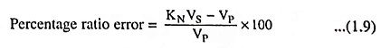
where
- KN is the nominal ratio-the ratio of rated primary voltage and rated secondary voltage.
The phase angle error δ is usually given in minutes and indicates by what small angle δ the secondary voltage VS departs from exact opposition to the applied primary voltage VP.
With the increase in the number of instruments and relays connected to the secondary of a PT, i.e., with the increase in burden of the secondary circuit, both of the errors will increase.
The ‘burden’ is the total external volt-ampere load on the secondary at rated secondary voltage. Where several loads (instruments and relays) are connected in parallel, it is usually sufficient to add their individual volt-amperes arithmetically to determine the total volt-ampere burden.
The ratio and phase angle errors are also influenced by the primary voltage. Operation in excess of 10% overvoltage may cause increased errors and excessive heating. However, if a PT has acceptable accuracy at its rated voltage, it is suitable over the range from zero to 110% of rated voltage.
The ratio and phase angle errors of any standard ASA PT are so small that they may be neglected for the protective relaying purpose if the burden is within the ‘thermal’ volt-ampere rating of the PT. This thermal VA rating corresponds to the full-load rating of the power transformer.
The rated burden of a PT is the VA burden which must not be exceeded if the transformer is to operate with its rated accuracy (this burden is indicated on the name plate and in the data sheet).
The limiting or maximum burden is the greatest VA load at which the PT will operate continuously without overheating its windings beyond the permissible limits. This burden is several times greater than the rated burden.
In practice, use is made of single-phase and three-phase potential transformers, the latter being of the two-winding or three-winding type.
Table 1.5 gives the classification of PTs according to their accuracy class and the corresponding limits of errors.
![]()
There are two types of potential transformers; the conventional wound type (or electromagnetic type) and the capacitor voltage (potential) transformer. For voltages exceeding 100 kV (phase) the conventional type of potential transformer becomes extremely expensive owing to the insulation requirements. For voltages above 100 kV a capacitor potential transformer, a combination of a capacitor potential divider
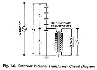
and a magnetic potential transformer (known as the intermediate transformer) of relatively small ratio is used. The circuit diagram is shown in Fig. 1.6. A stack of high-voltage capacitors forms the potential divider, the capacitors of the two sections being C1 and C2 respectively and Z is the burden. The voltage applied to the primary of the intermediate transformer T is usually about 10 kV. Both the potential divider and the intermediate transformer will have ratios and insulation requirements which are suitable for economical construction. The intermediate transformer must be of very small ratio error and phase angle to give satisfactory performance of the complete unit.
If the current flowing in the output or secondary circuit is negligible then
![]()