Delayed Automatic Gain Control:
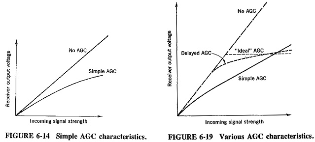
Delayed Automatic Gain Control: Simple AGC is clearly an improvement on no AGC at all, in that the gain of the receiver is reduced for strong signals. Unfortunately, as Figures 6-14 and 6-19 both show, even weak signals do not escape this reduction. Figure 6-19 also shows two other AGC curves. The first is an “ideal” AGC curve. Here, no Delayed Automatic Gain Control would be applied until signal strength was considered adequate, and after this point a constant average output would be obtained no matter how much more the signal strength rose. The second is the Delayed Automatic Gain Control curve. This shows that AGC bias is not applied until the signal strength has reached a predetermined level, after which bias is applied as with normal AGC, but more strongly. As the signal strength then rises, receiver output also rises, but relatively slightly. The problem of reducing the gain of the receiver for weak signals has thus been avoided, as with “ideal” AGC.
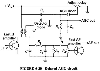
A very common method of obtaining Delayed Automatic Gain Control is shown in Figure 6-20. It uses two separate diodes: the detector and the AGC detector. These can be connected either to separate transformer winding, as shown, or both may be connected to the secondary without too much interference. As indicated, a positive bias is applied to the cathode of the AGC diode, to prevent conduction until a predetermined signal level has been reached. A control is often provided, as shown, to allow manual adjustment of the bias on the AGC diode, and hence of the signal level at which Delayed Automatic Gain Control is applied. If weak stations are mostly likely to be received, the delay control setting may be quite high (i.e., no AGO until signal level is fairly high). Nevertheless, it should be made as low as possible, to prevent overloading of the last IF amplifier by unexpected stronger signals.
The method just described works well with FETs, and also with bipolar transistors if the number of stages controlled is large enough. If, in the latter case, fewer than three stages are being controlled, it may not be possible to reduce the gain of the receiver sufficiently for very strong signals, because of collector leakage current. If that is so, a secondary method of Delayed Automatic Gain Control is sometimes used together with simple AGC, the overall result being not unlike Delayed Automatic Gain Control. A diode is here employed for variable damping, in a manner similar to that used in the ratio detector.
Variable sensitivity and selectivity:
The ratio of the highest to the lowest signal strengths which a communications receiver may have to cope with could be as high as 105 : 1. This means that the receiver must have sufficient sensitivity to amplify fully very weak signals, while also being capable of having its gain reduced by ACG action by a ratio of 105 : 1, or 100 dB, so as not to overload on the strongest signal. Even the best ACG system is not capable of this performance. Apart from the alarming variations in output that could occur, there is also the risk of overloading several of the IF amplifiers, especially the last one, and also the demodulator diode. To prevent the distortion which would follow, as well as possible permanent damage, the most sensitive communications receivers incorporate a sensitivity control. This control generally consists of a potentiometer which varies the bias on the RF amplifier and is, in fact, an RF gain control. The AGC is still present, but it now acts to keep the sensitivity of the receiver to the level determined by the setting of this control. The receiver is now considerably more versatile in handling varying input signal levels.
The selectivity, or to be more precise, the bandwidth, of the low-frequency IF amplifier may be made variable over a range that is commonly 1 to 12 kHz. The largest bandwidth permits reception of high-quality broadcasts; whereas the smallest (although it greatly impairs this quality) reduces noise and therefore increases intelligibility and will also reduce adjacent-channel interference. Variable selectivity is achieved in practice by switching in crystal, ceramic, or mechanical filters. A set is provided, any of which may be switched into the second IF stage to give bandwidths of 1, 2, 4, 6, 8, 10, and 12 kHz. Receivers designed for radiotelegraphy reception may have minimum bandwidths as low as 300 Hz.
A notch filter is sometimes found in a communications receiver. This is a wave trap, or a stop filter, designed to reduce receiver gain at some specific frequency so as to reject it. It often consists simply of a series-resonant circuit across one of the LF IF transformers. The frequency at which this trap is resonant will naturally be rejected since the load impedance of that amplifier will then be almost short-circuited. If the capacitor in the series-resonant circuit is made variable, the position of the notch can be adjusted so that any one adjacent spurious signal may be rejected on either side of the IF bandpass. A crystal gate may be used similarly. The versatility of a receiver is naturally enhanced, if it has a notch filter, variable selectivity and double conversion for suppressing unwanted nearby signals.
Blocking: If a radio receiver is tuned to a weak signal, naturally the developed AGC will be low and the front-end gain high. If a strong signal not too distant in frequency is now received, then unless it is properly rejected, it could develop substantial AGC voltage. Such a high AGC, caused by a spurious signal, could reduce the gain of the receiver, perhaps to the point of making the wanted signal inaudible. This situation is unwelcome; if the interfering signal is intermittent, it is intolerable. A receiver whose AGC system has very little reaction to the nearby spurious signals is said to have good blocking. A good way of showing how blocking is defined and measured is to state how it is quoted in receiver specifications. The Redifon R 551 is a receiver with very good blocking performance, quoted by the manufacturers as follows: “With a 1 mV EMF A0 (SSB, 1000 Hz tone) wanted signal, a simultaneous 6 V EMF A0 unwanted signal (at least 20 kHz from wanted signal) will not reduce the wanted AF output by more than 3 dB.”
Very high IF rejection of adjacent signals is needed to produce such excellent blocking performance. Yet this performance is required in SSB receivers and in all other instances of working in crowded frequency bands.