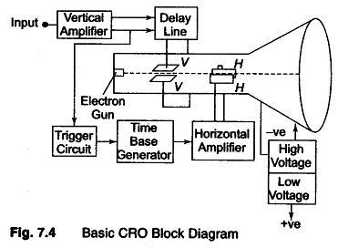
Block Diagram of Oscilloscope:
The major Block Diagram of Oscilloscope shown in Fig. 7.4, of a general purpose CRO, is as follows:
- CRT
- Vertical amplifier
- Delay line
- Time base
- Horizontal amplifier
- Trigger circuit
- Power Supply
The function of the various blocks are as follows.
1. CRT
This is the cathode ray tube which emits electrons that strikes the phosphor screen internally to provide a visual display of signal.
2. Vertical Amplifier
This is a wide band amplifier used to amplify signals in the vertical section.
3. Delay Line
It is used to delay the signal for some time in the vertical sections.
4. Time Base
It is used to generate the sawtooth voltage required to deflect the beam in the horizontal section.
5. Horizontal Amplifier
This is used to amplify the sawtooth voltage before it is applied to horizontal deflection plates.
6. Trigger Circuit
This is used to convert the incoming signal into trigger pulses so that the input signal and the sweep frequency can be synchronized.
7. Power Supply
There are two power supplies, a -ve High Voltage (HV) supply and a +ve Low Voltage (LV) supply. Two voltages are generated in the CRO. The +ve volt supply is from + 300 to 400 V. The -ve high voltage supply is from – 1000 to – 1500 V. This voltage is passed through a bleeder resistor at a few mA. The intermediate voltages are obtained from the bleeder resistor for intensity, focus and positioning controls.
Advantages of using -ve HV Supply:
- The accelerating anodes and the deflection plates are close to ground The ground potential protects the operator from HV shocks when making connections to the plates.
- The deflection voltages are measured wrt ground, therefore HV blocking or coupling capacitor are not needed, but low voltage rating capacitors can be used for connecting the HV supply to the vertical and horizontal
- Less insulation is needed between positioning controls and chasis.