Dual Trace Oscilloscope:
Figure 7.19 (a) shows a block diagram of Dual Trace Oscilloscope.
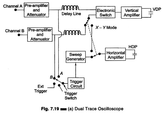
This CRO has a single electron gun whose electron beam is split into two by an electronic switch. There is one control for focus and another for intensity. Two signals are displayed simultaneously. The signals pass through identical vertical channels or vertical amplifiers. Each channel has its own calibrated input attenuator and i positioning control, so that the amplitude of each signal can be independpntly adjusted.
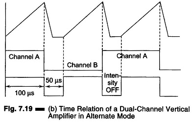
A mode control switch enables the electronic switch to operate in two modes. When the switch is in ALTERNATE position, the electronic switch feeds each signal alternately to the vertical amplifier. The electronic switch alternately connects the main vertical amplifier to channels A and B and adds a different dc component to each signal; this dc component directs the beam alternately to the upper or lower half of the screen. The switching takes place at the start of each new sweep of the sweep generator. The switching rate of the electronic switch is synchronized to the sweep rate, so that the CRT spot traces the channel A signal on one sweep and the channel B signal on the succeeding sweep [Fig. 7.19 (b)]
The sweep trigger signal is available from channels A or B and the trigger pick-off takes place before the electronic switch. This arrangement maintains the correct phase relationship between signals A and B.
When the switch is in the CHOP mode position, the electronic switch is free running at the rate of 100-500 kHz, entirely independent of the frequency of the sweep generator. The switch successively connects small segments of A and B waveforms to the main vertical amplifier at a relatively fast chopping rate of 500 kHz e.g. 1 μs segments of each waveform are fed to the CRT display (Fig. 7.19 (c)).
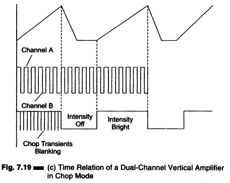
If the chopping rate is slow, the continuity of the display is lost and it is better to use the alternate mode of operation. In the added mode of operation a single image can be displayed by the addition of signal from channels A and B, i.e. (A + B), etc. In the X – Y mode of operation, the sweep generator is disconnected and channel B is connected to the horizontal amplifier. Since both preamplifiers are identical and have the same delay time, accurate X – Y measurements can be made.
Dual Trace Oscilloscope (0-15 MHz) Block Description Y-Channels:
A and B vertical channels are identical for producing the dual trace facility. Each comprises an input coupling switch, an input step attenuator, a source follower input stage with protection circuit, a pre-amplifier from which a trigger signal is derived and a combined final amplifier. The input stage protection circuit consists of a diode, which prevents damage to the FET transistors that could occur with excessive negative input potentials, and a resistor network which protects the input stage from large positive voltage swings.
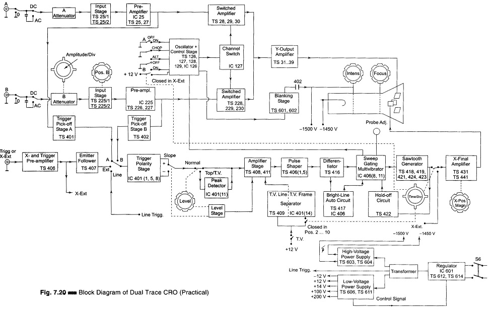
As the transistors are the balanced pre-amplifier stage, they share the same IC block. The resulting stabilization provides a measure of correction to reduce the drift inherent in high gain amplifiers. The trigger pick-off signal is taken from one side of the balanced pre-amplifier to the trigger mode switch, where either channel A or channel B triggering can be selected. The supply for the output of the pre-amplifier stage is derived from a constant current source controlled by the channel switching logic. Under the control of channel switching, signals from A and B channels are switched to the final amplifier. The combined balanced final amplifier is a direct coupled one to the Y-plates of the CRT (refer to Fig. 7.20).
Channel Switching:
The front panel A and B channel selection (push button or switch), controls an oscillator in the CHOP mode. For channel switching electronic switching logic and a F/F is used. When either A or B channels are selected, the F/F is switched to allow the appropriate channel.
In the ALTERNATE mode, a pulse from the sweep-gating multi vibrator via the electronic switching logic, switches the F/F, thus allowing A and B channels for alternate sweeps.
In the CHOP mode, the oscillator is switched via the logic stage to provide rapid switching of the channels via the F/F.
Triggering:
A triggering signal can be obtained from the vertical amplifier of Channels A and B from an external source or internally from the mains supply (LINE triggering). The triggering signal is selected and normally fed via the amplifier stage to the pulse shaper, which supplies well defined trigger pulses to the sweep-gating multivibrator for starting the sawtooth generator.
Triggering from the TV line and frame signals can be obtained from the sync separator and peak detector stages. The latter stage is switched into circuit in the TOP position.
Time Base:
The time base generator circuit operates on the constant current integrator principle.
The sweep-gating multi vibrator, triggered by pulses from the differentiator and auto circuits, starts the sawtooth generator. Sweep signals are fed to the final X-amplifier.
A gate pulse is supplied by the sweep-gating multi vibrator for unblanking the CRT during the forward sweep. In addition this pulse is supplied to an external socket for probe adjustment via a diode network.
X–Channel:
Under the control of diode switching from the TIME/DIV switch, the X- amplifier receives its input signal from either the time base sawtooth generator or from an external source (X-EXT input socket via the X and trigger pre-amplifier). The X-MAGN (x 5) circuit is incorporated in the X-final amplifier. The output of this amplifier is direct coupled to the horizontal deflection plates of the CRT.
Cathode–Ray Tube Circuit and Power Supply:
The high voltages required for the CRT, which has an acceleration potential of 1.5 kV, are generated by a voltage multiplier circuit controlled by a stabilized power supply. The CRT beam current is controlled by:
The intensity potentials network across the Extra High Tension (EHT) supply. During flyback (movement of electron beam from right to left) by the blanking pulses coming from the sawtooth generator via the beam blanking stages to blank the trace during right to left movement of the electron.
Regulation of the mains input voltage is achieved by a diode clipper network controlled by a signal fed back from an LED in the + 14 V rectifier supply.
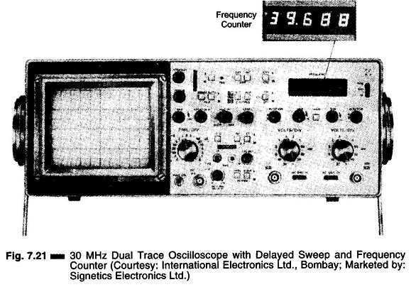
Dual Trace Oscilloscope Specifications:
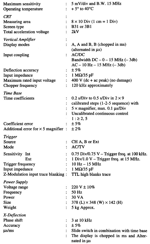
Figure 7.21 illustrates a 30 MHz Dual Trace Oscilloscope with Delayed Sweep and Frequency Counter (I.E. 234).