Oscilloscope as a Bridge Null Detector:
As a null detector for an ac bridge, the oscilloscope, unlike a meter used for the purpose, gives separate indications for reactive and resistive balances of the bridge.
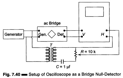
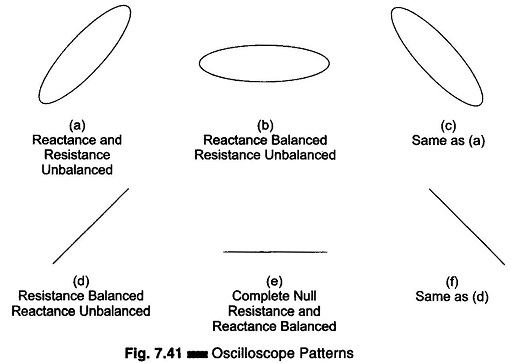
Figure 7.40 shows how an oscilloscope is connected to the bridge. Here T is the shielded transformed and C-R form an adjustable phase shift network. The generator voltage is applied to the horizontal input through a phase shifter, and simultaneously to the bridge input. The bridge output signal is applied to the oscilloscope vertical input. Figure 7.41 shows the type of pattern obtained.
Measurement Procedure:
Connect the circuit as shown in Fig. 7.40. With the bridge unbalanced, but with test components (R, C, L) connected to the unknown arm of the bridge, adjust R in the phase shifter to give an elliptical pattern on screen. Adjust the vertical and horizontal gain controls to obtain an ellipse of suitable height. Adjust the reactance control of the bridge, noting whether the ellipse tilts to the right or the left. When reactance balance is complete, i.e. reactance = 0, the ellipse will be horizontal.
Adjust the resistance (power factor, dissipation factor, or Q) control of the bridge, noting that the ellipse closes. At complete Null Detector (reactance and resistance, both balanced), a straight horizontal line is obtained. If the resistance is balanced while the reactance is not, tilted ellipse collapses, giving a single line trace tilted to the right or left.
A simpler but less effective way of using an oscilloscope as a null detector is to connect the bridge output to the vertical terminals and use the oscilloscope as a voltmeter to give its lowest reading at null.
Use of Lissajous Figures for Phase Measurement:
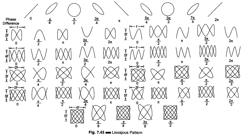
When two signals are applied simultaneously to an oscilloscope without internal sweep, one to the horizontal channel and the other to the vertical channel, the resulting pattern is a Lissajous figure that shows a phase difference between the two signals. Such patterns result from the sweeping of one signal by the other.
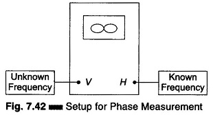
Figure 7.42 shows the test setup for phase measurement by means of Lissajous figures. Figure 7.43 shows patterns corresponding to certain phase difference angles, when the two signal voltages are sinusoidal, equal in amplitude and frequency.
A simple way to find the correct phase angle (whether leading or lagging) is to introduce a small, known phase shift to one of the inputs. The proper angle may be then deduced by noting the direction in which the pattern changes.