Standard Signal Generator Block Diagram and Working Principle:
A standard signal generator produces known and controllable voltages. It is used as power source for the measurement of gain, signal to noise ratio (S/N), bandwidth, standing wave ratio and other properties. It is extensively used in the testing of radio receivers and transmitters.
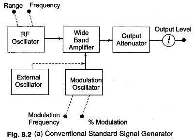
The instrument is provided with a means of modulating the carrier frequency, which is indicated by the dial setting on the front panel. The modulation is indicated by a meter. The output signal can be Amplitude Modulated (AM) or Frequency Modulated (FM). Modulation may be done by a sine wave, square wave, triangular wave or a pulse. The elements of a conventional standard signal generator block aiagram are shown in Fig. 8.2 (a).
Working Principle:
The carrier frequency is generated by a very stable RF oscillator using an LC tank circuit, having a constant output over any frequency range. The frequency of oscillations is indicated by the frequency range control and the vernier dial setting. AM is provided by an internal sine wave generator or from an external source.
(Modulation is done in the output amplifier circuit. This amplifier delivers its output, that is, modulation carrier, to an attenuator. The output voltage is read by an output meter and the attenuator output setting.)
Frequency stability is limited by the LC tank circuit design of the master oscillator. Since range switching is usually accomplished by selecting appropriate capacitors, any change in frequency range upsets the circuit design to some extent and the instrument must be given time to stabilize at the new resonant frequency.
In high frequency oscillators, it is essential to isolate the oscillator circuit from the output circuit. This isolation is necessary, so that changes occurring in the output circuit do not affect the oscillator frequency, amplitude and distortion characteristics. Buffer amplifiers are used for this purpose.
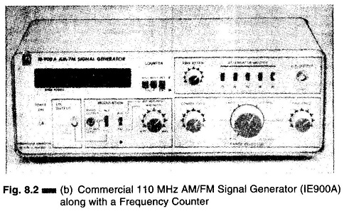
Figure 8.2(b) illustrates a commercial AM/FM signal generator (IE900A) having a frequency range from 100 kHz – 110 MHz, along with a frequency counter and TTL output.