Frequency Modulation Recording:
When a more accurate response to dc voltages is required, an Frequency Modulation Recording system is generally used. In this FM system, the input signal is used to frequency modulate a carrier, i.e. the carrier signal is frequency modulated by the input signal (FM modulation), which is then recorded on the tape in the usual way.
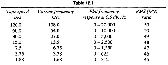
The central frequency is selected with respect to the tape speed and frequency deviation selected for the tape recorders is ± 40% about the carrier frequency.
The reproduce head reads the tape in the usual way and sends a signal to the FM demodulator and low pass filter, and the original signal is reconstructed. The signal to noise ratio (S/N) of an FM recorder is of the order of 40 – 50 db, with an accuracy of less then ± 1%.
This ± 1 db flat frequency response of Frequency Modulation Recording can go as high as 80 kHz at 120 in/s tape speed, when using very high carrier frequencies (above 400 kHz).
When high frequency (HF) is not needed, and with a view to conserving tape. A tape speed range selector is generally provided. When the tape speed is changed, the carrier frequency also changes in the same proportion. Therefore, no matter what tape speed is being used, the recorded wavelength of a given dc input remains the same, since ± 40% full scale frequency deviation is utilized in all cases. A common set of specifications are given in Table 12.1.
Input to the tape recorders is generally at the 1 V level, and so most transducers require amplification before recording.
An FM recording system is illustrated in Fig. 12.11. In this system a carrier oscillator frequency fc, called the centre frequency, is modulated by the level of the input signal.
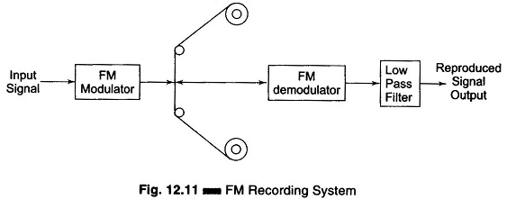
When there is no input signal, i.e. zero input, the modulation is at centre frequency fc. If a positive input signal is applied, the frequency deviates from the centre frequency by some amount in a certain direction; the application of a negative input voltage deviates the carrier frequency in the opposite direction.
The output of the modulation, which is fed to the tape, is a signal of constant frequency for dc inputs, and varying frequency for ac inputs. The variation of frequency is directly proportional to the amplitude of the input signal. On playback, the output of the reproduce head is demodulated and fed through a low pass filter which removes the carrier and other unwanted frequencies reproduced due to the modulation process.
The operation of FM modulation can be easily checked by applying a known input voltage and measuring the output frequency with an electronic counter. This signal is applied to the tape with no further conditioning, as the signal is independent of the amplitude. The FM demodulator converts the difference between the centre frequency and the frequency on the tape, to a voltage proportional to the difference in the frequencies. This system can thus record frequencies from dc to several thousand Hertz. Residual carrier signals and out of band noise are removed by a low pass filter.
Advantages of FM Recording:
- Frequency Modulation Recording is useful primarily when the dc component of the input signal is to be preserved.
- This system has a wide frequency range and can record from dc voltages to several kHz.
- There is no drop-out effect due to inhomogeneties of the tape material.
- Independent of amplitude variations, and accurately reproduces the waveform of the input signal.
- Used extensively for recording voltages derived from non-electrical quantities, such as force, acceleration and pressure.
- It is extremely useful for multiplexing in an instrumentation system.
Disadvantages of FM Recording:
- Frequency Modulation Recording is extremely sensitive to tape speed fluctuations.
- FM recording circuitry is more complicated than that of direct recording systems.
- FM system has a limited frequency response.
- It requires a high tape speed.
- It requires a high quality of tape transport and speed control.
Pulse Duration Modulation:
Pulse width modulation is also called pulse duration modulation (PDM). In this system, the amplitude and the starting time of each pulse is kept fixed, but the width of the pulse is made proportional to the amplitude of the signal at that instant. This type of system is mostly used for Digital recording.