Generation of Amplitude Modulation:
There are two types of devices in which it may be necessary to the Generation of Amplitude Modulation. The first of these, the AM transmitter, generates such high powers that its prime requirement is efficiency, so quite complex means of AM generation may be used. The other device is the (laboratory) AM generator. Here AM is produced at such a low power level that simplicity is a more important requirement than efficiency. Although the methods of generating AM described here relate to both applications, emphasis will be put on methods of generating high powers.
Basic Requirements:
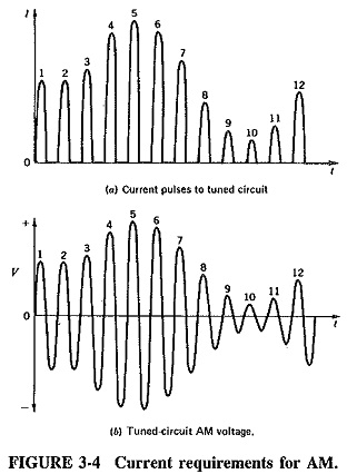
In order to generate the AM wave of Figure 3-4b, it is necessary merely to apply the series of current pulses of Figure 3-4a to a tuned (resonant) circuit. Each pulse, if it were the only one, would initiate a damped oscillation in the tuned circuit. The oscillation would have an initial amplitude proportional to the size of the current pulse and a decay rate dependent on the time constant of the circuit. Since a train of pulses is fed to the tank circuit here, each pulse will cause a complete sine wave proportional in amplitude to the size of this pulse. This will be followed by the next sine wave, proportional to the size of the next applied pulse, and so on. Bearing in mind that at least 10 times as many pulses per audio cycle are fed to a practical circuit as are shown in Figure 3-4, we see that an extremely good approximation of an AM wave will result if the original current pulses are made proportional to the modulating voltage. The process is known as the flywheel effect of the tuned circuit, and it works best with a tuned circuit whose Q is not too low.
It is possible to make the output current of a class C amplifier proportional to the modulating voltage by applying this voltage in series with any of the dc supply voltages for this amplifier. Accordingly, cathode (or emitter), grid (or base) and anode (plate or collector) modulation of a class C amplifier are all possible, as is any combination of these methods. Each has its own applications, advantages and drawbacks.
In an AM transmitter, Generation of Amplitude Modulation can be generated at any point after the radio frequency source. As a matter of fact, even a crystal oscillator could be amplitude-modulated, except that this would be an unnecessary interference with its frequency stability. If the output stage in a transmitter is plate-modulated (or collector-modulated in a lower-power transmitter), the system is called high-level modulation. If modulation is applied at any other point, including some other electrode of the output amplifier, Then so-called low-level modulation is produced. Naturally the end product of both systems is the same, but the transmitter circuit arrangements are different.
It is not feasible to use plate modulation of the output stage in a television transmitter, because of the difficulty in generating high video (modulating) powers at the large bandwidths required. Grid modulation of the output stage is the highest level of modulation employed in TV transmitters. It is called “high-level” modulation in TV broadcasting, and anything else is then called “low-level” modulation.
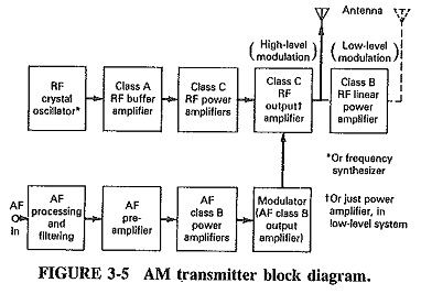
Figure 3-5 shows a typical block diagram of an AM transmitter, which may be either low-level- or high-level-modulated. There are a lot of collation features. Both have a stable RF source and buffer amplifiers followed by RF power amplifiers. In both types of transmitters the audio voltage is processed, or filtered, so as to occupy the correct bandwidth (generally 10 kHz), and compressed somewhat to reduce the ratio of maximum to minimum amplitude. In both Generation of Amplitude Modulation systems audio and power audio frequency (AF) amplifiers are present, culminating in the modulator amplifier, which is the highest-power audio amplifier. In fact, the only difference is the point at which the modulation takes place. To exaggerate the difference, an amplifier is shown here following the modulated RF amplifier for low-level modulation, and it is seen that this must be a linear RF amplifier, i.e., class B. Remember that this would also have been called low-level modulation if the modulated amplifier had been the final one, modulated at any electrode other than the plate (or collector).
It follows that the higher the level of Generation of Amplitude Modulation, the larger the audio power required to produce modulation. The high-level system is definitely at a disadvantage in this regard. On the other hand, if any stage except the output stage is modulated, each following stage must handle sideband power as well as the carrier. All these subsequent amplifiers must have sufficient bandwidth for the sideband frequencies. As seen in Figure 3-5, all these stages must be capable of handling Generation of Amplitude Modulation variations caused by the Generation of Amplitude Modulation. Such stages must be class A and consequently are less efficient than class C amplifiers.
Each of the systems is seen to have one great advantage; low modulating power requirements in one case, and much more efficient RF amplification with simpler circuit design in the other. It has been found in practice that a plate-modulated class C amplifier tends to have better efficiency, lower distortion and much better power-handling capabilities than a grid-modulated amplifier. Because of these considerations, broadcast AM transmitters today almost invariably use high-level modulation, and TV transmitters use grid modulation of the final stage. Other methods may be used in low-power and miscellaneous applications, AM generators and test instruments.
Broadcasting is the major application of AM, with typical output powers ranging from dozens to hundreds of kilowatts.
Grid-Modulated Class C Amplifier:
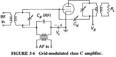
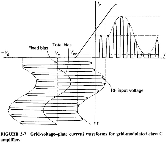
A class C amplifier may be modulated by the introduction of the modulating voltage in series with the grid bias, as shown in Figure 3-6. The modulating voltage is superimposed on the fixed battery bias. Therefore, the amount of bias is proportional to the amplitude of the modulating signal and varies at a rate equal to the modulating frequency. This is shown in Figure 3-7, as is the RF input voltage superimposed on the total bias. The resulting plate current flows in pulses, the amplitude of each pulse being proportional to the instantaneous bias and therefore to the instantaneous modulating voltage. As in Figure 3-4, the application of these pulses to the tuned tank circuit will yield Generation of Amplitude Modulation.
As the waveform shows, this system will operate without distortion only if the transfer characteristic of the triode is perfectly linear. Because this can never be so, the output must be somewhat distorted (more so, in fact, than from a plate-modulated amplifier). It turns out also that the plate efficiency is lower as a result of the need to arrange the input conditions, as shown in Figure 3-7, so that grid current does not flow in the absence of modulation (this is so that full modulation may be obtained when desired, and it is caused by the geometry of the figure). Reference to the operation of the class C amplifier shows that it operates at maximum efficiency only when the grid is driven to the limit, and, as this is not the case here, efficiency suffers.
Because of these bias conditions, the maximum output power from a grid-modulated amplifier is much less than that obtainable from the same tube if it is unmodulated (or plate-modulated). The disadvantages of grid modulation are counterbalanced by the lower modulating power needed in comparison with plate modulation.
The harmonics generated as a result of the nonlinearity of the transfer characteristic may be reduced by operating the amplifier in push-pull. Grid modulation is not used to generate AM for transmission unless other factors are involved.
Plate-Modulated Class C Amplifier:
The plate-modulated class C amplifier is the standard and most widely used method of obtaining Generation of Amplitude Modulation for broadcasting and other high-power transmission applications. The audio voltage is placed in series with the plate-supply voltage of a class C amplifier, whose plate current is varied in accordance with the modulating signal. The amplifier most frequently modulated in this manner is the final power amplifier of the transmitter (more simply termed the final or the PA).
The output of the modulating amplifier is normally applied to the PA through an audio output (modulating) transformer. This system is sometimes called anode-6 modulation, i.e., anode modulation of the output power amplifier and class B operation of the modulator, the latter having transformer output. The transformer permits the use of a class B modulator, giving, good audio efficiency. It also allows 100 percent modulation to be achieved, since the output of the modulator can be stepped up to any value required. As a result of these considerations, this modulation system is employed in a vast majority of AM broadcasting transmitters.
Transformer modulation using triode:
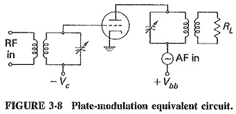
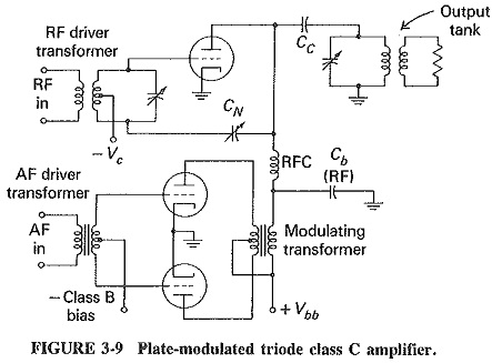
The equivalent circuit of Figure 3-8 has been transformed into the practical circuit of Figure 3-9 by the inclusion of the modulator with its transformer output. Neutralization is also shown, as it was for the grid-modulated amplifier, since it will certainly be necessary to avoid the Miller effect in a triode at high frequencies. A shunt fed C amplifier is shown mainly to simplify the explanation; it may or may not be used in practice. Note that a choke is placed in series with the modulation transformer to protect it from RF damage.
It is seen that the same supply voltage Vbb is used for both the PA and the modulator. This means that the peak modulator output voltage (per tube) is made less than Vbb to avoid distortion. A value of VAF = 0.7 Vbb is optimum. Since the peak-topeak modulator primary voltage is now 1.4Vbb, and an audio voltage equal to Vbb is required to produce full modulation, the transformer turns ratio in this case will be 1.4:1. Although a fixed bias supply Vcc is shown in Figure 3-9, self-bias may be used in the form of leak-type bias. This fact results in better operation.
The first waveform of Figure 3-10 shows the total plate voltage applied to the class C amplifier, and the second shows the resulting plate current. This is seen to be a series of pulses governed by the size of the modulating voltage, and when these are applied to the tank circuit, the modulated wave of the waveform of Figure 3-10c results. What happens here is obviously very similar to what happened with the grid-modulated amplifier, except that the appropriate train of current pulses is obtained by a different method, which also has the virtue of being more linear.
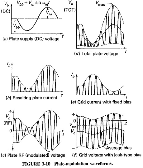
The last three waveforms of Figure 3-10 are used not so much to explain how the circuit generates AM, but to describe the behavior of the circuit itself. The waveform of Figure 3-10d shows the total voltage appearing between plate and cathode and is obtained by superimposing the RF-modulated voltage of Figure 3-10c on the combined supply voltage of Figure 3-10a. On the circuit of Figure 3-9, the RF voltage appears across the primary coil of the output tank, while the supply voltage is blocked by the coupling capacitor Cc. The purpose of Figure 3-10d is to show how much higher than Vbb the peak plate voltage may rise. At 100 percent modulation, in fact, the peak of the unmodulated RF voltage is nearly 2Vbb, and the positive peak of the modulated cycle rises to twice that. Thus the maximum plate voltage may rise to nearly 4Vbb in the plate-modulated amplifier. Care must be taken to ensure that the tube used is capable of withstanding such a high voltage.
The waveform of Figure 3-10e demonstrates that the grid current of the modulated amplifier varies during the modulating cycle, although the RF driving voltage does not. When the plate supply voltage falls at the negative modulation peak, the plate is then only moderately positive, and since the grid is also driven positive, the current in the grid now increases rather significantly. At the positive peak of modulation, the reverse applies, and grid current falls. Note that the change is not sinusoidal since the current rise greatly exceeds the fall. If this situation is left unchecked, two unpleasant effects result. First, the driver may become overloaded when grid current rises, resulting in the distortion of the output wave. Second, the grid of the PA will almost certainly melt!
Two cures are available, and Figure 3-10f shows the result of the better of the two. The first is to have a driver with poor regulation so that grid current is incapable of rising, whereas the better cure is to use grid leak bias to achieve limiting similar to that used by the amplitude limiter in FM receivers. As grid current now tends to increase, grid bias also rises, becoming more negative and tending to reduce grid current. For any original value of grid current a balance is now struck so that although grid current still rises, this rise is much less marked and can be well within acceptable limits. At the positive modulation peak, grid current would tend to fall, but this fall is now reduced by a simultaneous reduction in negative bias, so that the grid-current waveform now looks like a much-flattened version of Figure 3-10e.
Instead of being constant, grid voltage now varies as in Figure 3-101 This aids the modulation process because the grid is now made more positive at the time of peak plate current. It now becomes easier to obtain such a high value of plate current, and so distortion at the positive modulation peak is prevented. Considered from another point of view, the waveform of Figure 3-10f is seen to be very similar to the input wave for a grid-modulated amplifier, as in Figure 3-7. A grid- and plate-modulated amplifier which is more efficient and less distorted is obtained.
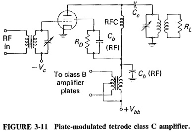
Plate modulation of tetrode:
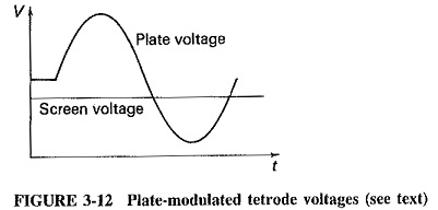
If a screen-grid tube is used as a plate-modulated class C amplifier, the same good results are obtainable, provided that the extra factors are considered. The fact that screen current increases enormously, if screen voltage exceeds plate voltage, must certainly be taken into account.. If it were not, this situation could occur here once every cycle of modulating voltage (if the screen were merely connected to Vbb through a dropping resistor). This is illustrated in Figure 3-12. The system would become very inefficient and the tube short-lived, but the situation is easily avoided by modulation of the screen simultaneously with the plate, as shown on the circuit of Figure 3-11.
The same stratagem avoids the difficulty of trying to vary the plate current of a screen-grid tube by adjusting the plate voltage only (while keeping the screen voltage constant). We thus have a high-level system, which is simultaneously plate-, screen-and even grid-modulated when leak-type bias is used and has good characteristics, properties and a plate efficiency that can exceed 90 percent in practice.
Modulated Transistor Amplifiers:
Modern high-power AM transmitters tend to use transistors at the lower power levels, so that transistor RF and AF exciters are common. The output stages, and generally the drivers, of such transmitters use tubes. All-transistor transmitters are used for lower-power applications with a few kilowatts output obtainable if transistors in parallel are employed. As a result, modulated transistor amplifiers almost all have a push-pull final amplifier for maximum power output.
The modulation methods for transistor amplifiers are counterparts of those used with tubes. Collector and base modulation of class C transistor amplifiers are both popular, having the same properties and advantages as the corresponding tube circuits. The result is that once again collector modulation is generally preferred. A typical circuit is shown in Figure 3-13.
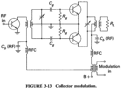
Collector modulation has the advantages over base modulation of better linearity, higher collector efficiency and higher power output per transistor. As expected, it requires more modulating power. In addition, collector saturation prevents 100 percent modulation from being achieved with just the collector being modulated, so that a compound form of modulation is used in a number of cases. Figure 3-13 shows one of the alternatives. Here the driver as well as the output amplifier is collector-modulated, but apart from that the circuit is analogous to the tube circuit. The other alternative is to employ collector and base modulation of the same amplifier. This method is often used with tubes when grid leak bias is incorporated. Although leak-type bias might again be employed for this purpose, there is the danger that if sufficient bias action is used to permit base modulation, the bias will become excessive, and power output will drop. Simultaneous base and collector modulation, similar to that shown in Figure 3-13, is preferable. Note finally that drain- and gate-modulation of field-effect-transistor (FET) amplifiers is equally feasible and is used in some systems.