Amplitude Limiter in FM Receiver:
In order to make full use of the advantages offered by FM, a demodulator must be preceded by an Amplitude Limiter in FM Receiver, as discussed earlier, on the grounds that any amplitude changes in the signal fed to the FM demodulator are spurious. (This does not apply to a receiver with a ratio detector which, as is shown in Section 6-4.4, provides a fair amount of limiting.) They must therefore be removed if distortion is to be avoided. The point is significant, since most FM demodulators react to amplitude changes as well as frequency changes. The limiter is a form of clipping device, a circuit whose output tends to remain constant despite changes in the input signal. Most limiters behave in this fashion, provided that the input voltage remains within a certain range. The common type of limiter uses two separate electrical effects to provide a relatively constant output. There are leak-type bias and early (collector) saturation.
Operation of the Amplitude Limiter:
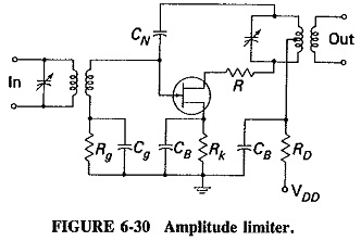
Figure 6-30 shows a typical FET Amplitude Limiter in FM Receiver. Examination of the dc conditions shows that the drain supply voltage has been dropped through resistor RD. Also, the bias on the gate is leak-type bias supplied by the parallel Rg – Cg combination. Finally, the FET is shown neutralized by means of capacitor CN, in consideration of the high frequency of operation.
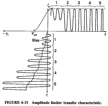
Leak-type bias provides limiting, as shown in Figure 6-31. When input signal voltage rises, current flows in the Rg – Cg bias circuit, and a negative voltage is developed across the capacitor. It is seen that the bias on the FET is increased in proportion to the size of the input voltage. As a result, the gain of the amplifier is lowered, and the output voltage tends to remain constant.
Although some limiting is achieved by this process, it is insufficient by itself, the action just described would occur only with rather large input voltages. To overcome this, early saturation of the output current is used, achieved by means of a low drain supply voltage. This is the reason for the drain dropping resistor of Figure 6-30. The supply voltage for a limiter is typically one-half of the normal dc drain voltage. The result of early saturation is to ensure limiting for conveniently low input voltages.
It is possible for the gate-drain section to become forward-biased under saturation conditions, causing a short circuit between input and output. To avert this, a resistance of a few hundred ohms is placed between the drain and its tank. This is R of Figure 6-30.
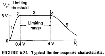
Figure 6-32 shows the response characteristic of the Amplitude Limiter in FM Receiver. It indicates clearly that limiting takes place only for a certain range of input voltages, outside which output varies with input. Referring simultaneously to Figure 6-31, we see that as input increases from value 1 to value 2, output current also rises. Thus no limiting has yet taken place. However, comparison of 2 and 3 shows that they both yield the same output current and voltage. Thus limiting has now begun. Value 2 is the point at which limiting starts and is called the threshold of limiting. As input increases from 3 to 4, there is no rise in output; all that happens is that the output current flows for a somewhat shorter portion of the input cycle. This, of course, suggests operation like that of a class C amplifier. Thus the flywheel effect of the output tank circuit is used here also, to ensure that the output voltage is sinusoidal, even though the output current flows in pulses. When the input voltage increases sufficiently, as in value 5, the angle of output current flow is reduced so much that less power is fed to the output tank. Therefore the output voltage is reduced. This happens here for all input voltages greater than 4, and this value marks the upper end of the limiting range, as shown in Figure 6-32.
Performance of the Amplitude Limiter:
It has been shown that the range of input voltages over which the Amplitude Limiter in FM Receiver will operate satisfactorily is itself limited. The limits are the threshold point at one end and the reduced angle of output current flow at the other end. In a typical practical limiter, the input voltage 2 may correspond to 0.4 V, and 4 may correspond to 4 V. The output will be about 5 V for both values and all voltages in between (note that all these voltages are peak-to-peak values). The practical limiter will therefore be fed a voltage which is normally in the middle of this range, that is, 2.2 V peak-to-peak or approximately 0.8 V rms. It will thus have a possible range of variation of 1.8 V (peak-to-peak) within which limiting will take place. This means that any spurious amplitude variations must be quite large compared to the signal to escape being limited.
Further limiting It is quite possible for the Amplitude Limiter in FM Receiver described to be inadequate to its task, because signal-strength variations may easily take the average signal amplitude outside the limiting range. As a result, further limiting is required in a practical FM receiver.
Double limiter:
A double limiter consists of two amplitude limiters in cascade, an arrangement that increases the limiting range very satisfactorily. Numerical values given to illustrate limiter performance showed an output voltage (all values peak-to-peak, as before) of 5 V for any input within the 0.4- to 4-V range, above which output gradually decreases. It is quite possible that an output of 0.6 V is not reached until the input to the first limiter is about 20 V. If the range of the second limiter is 0.6 to 6 V, it follows that all voltages between 0.4 and 20 V fed to the double limiter will be limited. The use of the double limiter is seen to have increased the limiting range quite considerably.
Automatic gain control (AGC):
A suitable alternative to the second limiter is automatic gain control. This is to ensure that the signal fed to the limiter is within its limiting range, regardless of the input signal strength, and also to prevent overloading of the last IF amplifier. If the limiter used has leak-type bias, then this bias voltage will vary in proportion to the input voltage (as shown in Figure 6-31) and may therefore be used for AGC. Sometimes a separate AGC detector is used, which takes part of the output of the last IF amplifier and rectifies and filters it in the usual manner.