Block Diagram of Sweep Generator:
Block Diagram of Sweep Generator – It provides a sinusoidal output voltage whose frequency varies smoothly and continuously over an entire frequency band, usually at an audio rate. The process of frequency modulation may be accomplished electronically or mechanically.
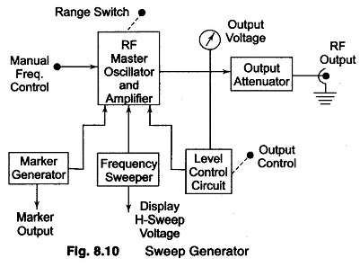
It is done electronically by using the modulating voltage to vary the reactance of the oscillator tank circuit component, and mechanically by means of a motor driven capacitor, as provided for in a modern laboratory type signal generator. Figure 8.10 shows a basic block diagram of a sweep generator.
The frequency sweeper provides a variable modulating voltage which causes the capacitance of the master oscillator to vary. A representative sweep rate could be of the order of 20 sweeps/second. A manual control allows independent adjustment of the oscillator resonant frequency.
The frequency sweeper provides a varying sweep voltage for synchronization to drive the horizontal deflection plates of the CRO. Thus the amplitude of the response of a test device will be locked and displayed on the screen.
To identify a frequency interval, a marker generator provides half sinusoidal waveforms at any frequency within the sweep range. The marker voltage can be added to the sweep voltage of the CRO during alternate cycles of the sweep voltage, and appears superimposed on the response curve.
The automatic level control circuit is a closed loop feedback system which monitors the RF level at some point in the measurement system. This circuit holds the power delivered to the load or test circuit constant and independent of frequency and impedance changes. A constant power level prevents any source mismatch and also provides a constant readout calibration with frequency.
