Amplifier Testing:
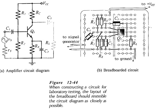
Preparation – Transistor Amplifier Testing and other circuits should be tested in a methodical fashion; otherwise the results obtained may be useless. The circuit should first be carefully constructed in bread-board form, placing the components to resemble the circuit diagram as closely as possible. This makes testing and troubleshooting much easier than when the layout is untidy. Figure 12-44(a) shows a CE circuit, and Fig. 12-44(b) illustrates a suitable circuit layout on a plug-in type breadboard.
Instability:
After the circuit has been constructed, the power supply should be set to the appropriate voltage and then connected and switched on. An oscilloscope should be connected to monitor the output of the Amplifier Testing to check that the circuit is not oscillating. If the circuit is oscillating, the oscillations must be stopped before proceeding further. For example, dc voltage measurements made on an oscillating circuit have absolutely no value.
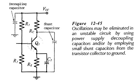
Amplifier Testing instability can be the result of incorrect design or poor circuit layout. It can also be caused by feedback along the conductors from the power supply to the circuit. To stabilize an unstable amplifier, commence by connecting a 0.01 μF (or 0.1 μF, if necessary) decoupling capacitor from the positive supply line to ground, (Fig. 12-45). Where a plus-minus supply is used, connect capacitors from each supply line to ground. The capacitors must be installed right on the breadboard. It is useless to place them at power supply terminals.
If the circuit is still unstable, small shunt capacitors should be connected from the transistor collector terminals to ground, or between collector and base, (Fig. 12-45). Start with 50 pF capacitors for this purpose, and increase the capacitance in steps to about 300 pF, as necessary. Normally, these capacitors should not be part of the final circuit. They are usually installed temporarily (if they are required) only until the source of the circuit instability is located.
DC Voltage Measurements:
Once it is established that the circuit is stable, the next step is to measure the dc voltage levels at all transistor terminals. An electronic voltmeter should be used, and every dc voltage level should be measured with respect to ground. Some electronic voltmeters have their common terminal capacitor-coupled to ground. So, it is best to keep the voltmeter common terminal grounded at all times. If the dc voltages are not satisfactory, they must be corrected before proceeding further. Even when the voltage levels are not exactly as designed, it might be possible to proceed.
The measured dc voltage levels should at least show that every BJT base-emitter junction is forward biased by the appropriate amount (approximately 0.7 V for silicon transistors and 0.3 V for germanium devices). The measurements should also show a minimum of 2 V for each collector-emitter Voltage drop.
AC Testing:
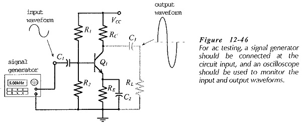
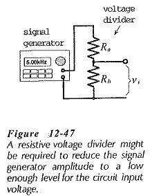
When satisfactory dc levels are established throughout the circuit, ac tests may proceed. Connect a signal generator to the input, and connect a two-channel oscilloscope to simultaneously monitor the input and output voltage waveforms, (Fig. 12-46). Adjust the signal frequency to somewhere around the middle of the amplifier bandwidth, and adjust the signal amplitude to give maximum undistorted output voltage. If the signal generator amplitude cannot be set to a low enough level to give an undistorted output, a resistive voltage divider should be employed to further reduce the signal amplitude, (see Fig. 12-47).
The Amplifier Testing input and output voltage amplitudes (vi and vo) can be measured and the voltage gain can be calculated as Av = vo/ vi. When a two-stage circuit is being tested, one oscilloscope probe may be moved to monitor the output voltage (o) of the first stage. The gain of the first stage is Av1 = vo1/vi, and that of the second stage is Av2 = vo/vo1
With the oscilloscope monitoring the input and output waveforms, the frequency response of the circuit may be investigated. The signal voltage level should be maintained constant, and the signal frequency adjusted in convenient steps. At each frequency, vo should be measured and Av calculated. The upper and lower cutoff frequencies are found where vo drops to 0.707 of its normal (mid-frequency) level with vi still at it normal level.
Input and Output Impedances:
The Amplifier Testing input and output impedances should normally be measured with the signal frequency at the middle of the bandwidth. The simplest way to measure the input impedance is to connect a resistor (not a decade box) in series with the circuit input terminal and the signal source, (see Fig. 12-48(a)]. When the ac output voltage drops to half its normal level, the series-connected resistor equals the input impedance. If the output voltage change is other than half, the input resistance can be calculated using the voltage divider equation.
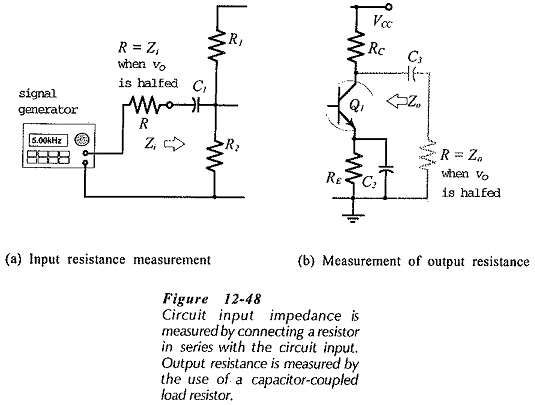
The output impedance of a circuit may be determined by connecting a resistor as a capacitor-coupled load at the circuit output, [Fig. 12-48(b). The ac output voltage is once again halved when the load resistance equals the circuit output impedance.